Robot cleaner, robot cleaning system having the same, and method for operating a robot cleaner

a robot cleaner and cleaning system technology, applied in the field of robot cleaners, can solve the problems of unwound cleaning, unsatisfactory automatic cleaning, and only worsening the cleaning state, so as to avoid any undesired cleaning operation and improve the cleaning process

Active Publication Date: 2016-09-29
LG ELECTRONICS INC
View PDF12 Cites 70 Cited by
  • Summary
  • Abstract
  • Description
  • Claims
  • Application Information

AI Technical Summary

Benefits of technology

[0011]A further object of the present disclosure is to provide a robot cleaner and a method for operating the robot cleaner allowing an improved cleaning process avoiding any unde...

Problems solved by technology

However, because robot cleaners often operate when the user is not present, there might be situations in which automatic cleaning is not desired.
For example, automatic cleaning may be undesir...

Method used


Image

  • Robot cleaner, robot cleaning system having the same, and method for operating a robot cleaner
  • Robot cleaner, robot cleaning system having the same, and method for operating a robot cleaner
  • Robot cleaner, robot cleaning system having the same, and method for operating a robot cleaner

Examples


second embodiment

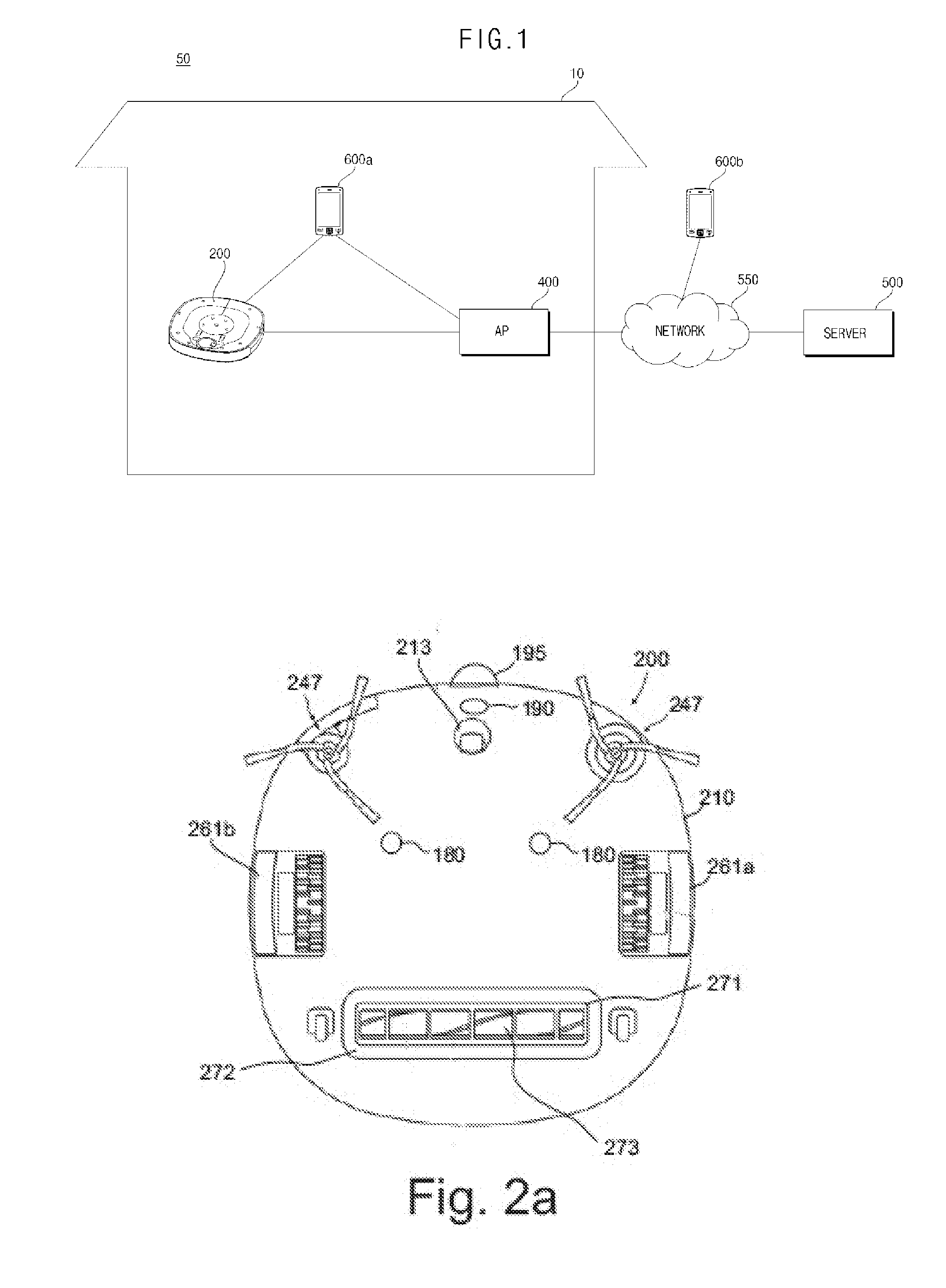
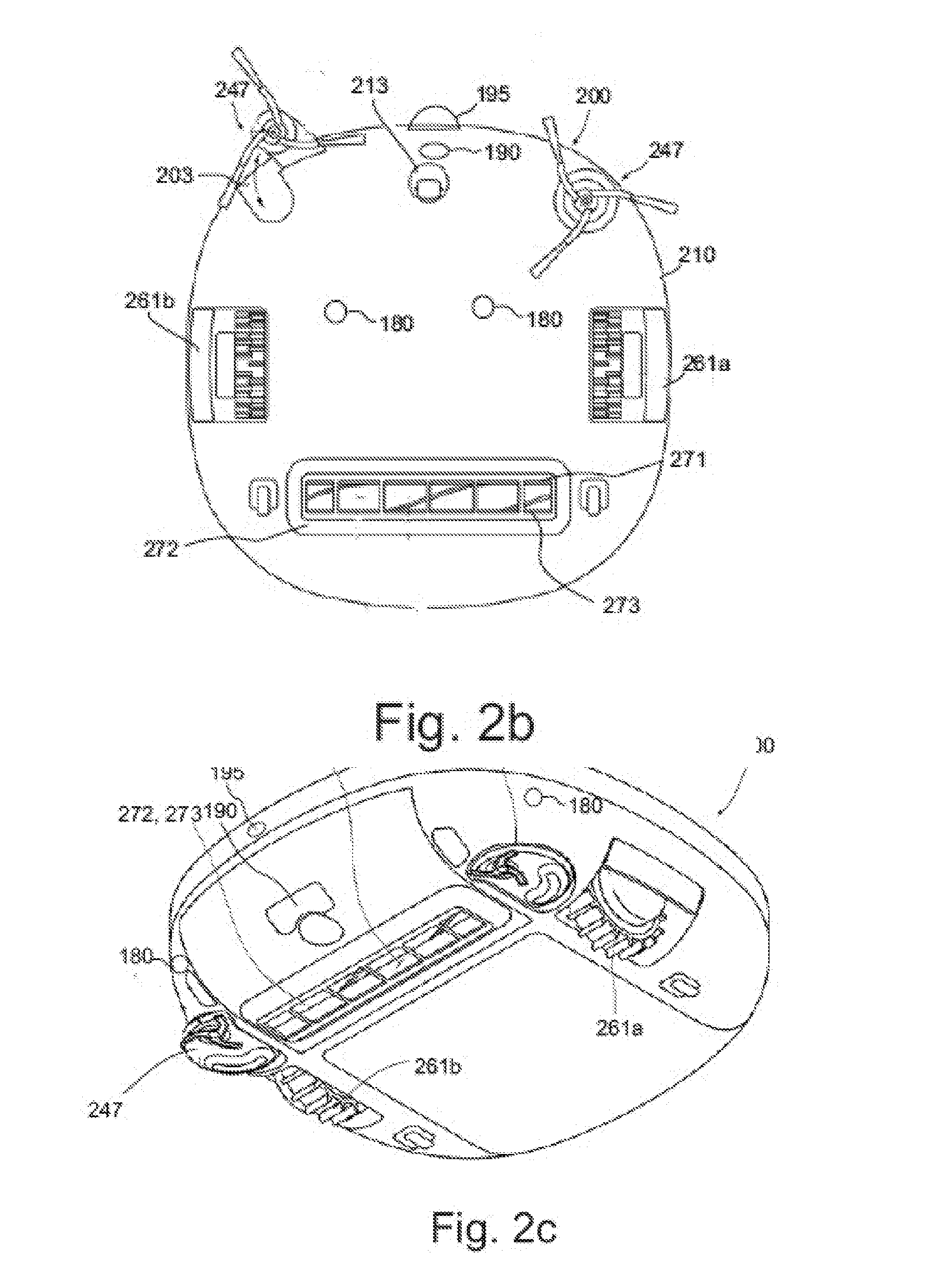
[0058]Furthermore, the robot cleaner may have a front camera 195 for taking a picture of the floor to be cleaned in front of the robot cleaner 200. Furthermore, the robot cleaner may have a bottom camera190 for taking a picture of the floor below the bottom of the main body. Moreover, as shown in the second embodiment a single camera 230 for taking pictures in several directions may be used and accommodated in a transparent housing.

[0059]FIG. 2(d) is a perspective view of a robot cleaner in accordance with another embodiment of the present disclosure. FIG. 2(e) is a bottom view of the robot cleaner of FIG. 2(d). FIG. 2 (f) is an exploded perspective view of the robot cleaner of FIG. 2(a).

[0060]With reference to FIGS. 2(d), 2(e), and 2(f), the robot cleaner 200 may include a main body 210 provided with a lower opening 210h which is opened toward the floor. The main body 210 may travel about an area to be cleaned (hereinafter, “cleaning area”) as a left wheel 261a and a right wheel 26...

first embodiment

[0069]The internal components of the robot cleaner 200 shown in FIGS. 2a, 2b and 2c and as shown in FIGS. 2d, 2e, and 2f, will be explained in further detail below with reference to FIG. 4.

[0070]With reference to FIG. 4, the robot cleaner 200 may include a position sensor unit 220, a communication unit 222 for communication with other external devices, a camera 230, 190, 195, a display unit 231 to display the operating state of the robot cleaner 200, a memory 243, a cleaning unit 245, an audio input unit 252, an audio output unit 254, a controller 270 to control the inside of the robot cleaner 200, a traveling unit 280 to move the robot cleaner 20, an input unit 295 for user input, a sensor unit 180, and a battery 199.

[0071]As shown in FIG. 4, the controller 270 included in the cleaner 200 may be connected to all components for controlling the internal or external components of the robot cleaner and for processing the inputs and outputs of the robot cleaner. The controller 270 may ...


PUM


Abstract

Disclosed herein are a robot cleaner and a robot cleaning system having the same. The robot cleaner includes a main body, a traveling unit configured to move the main body, a cleaning unit configured to execute cleaning, a camera configured to capture an image including foreign substances, a communication unit configured to exchange data with a mobile terminal or a server, and a controller configured to control transmission of the image including the foreign substances and image related information to the mobile terminal or the server and to execute cleaning of an area around the foreign substances based on cleaning execution information regarding the foreign substances or to execute no cleaning of the area around the foreign substances based on cleaning avoidance information regarding the foreign substances, transmitted from the mobile terminal or the server. Thereby, the robot cleaner may selectively clean foreign substances.

Description

CROSS-REFERENCE TO RELATED APPLICATION[0001]This application claims the benefit of Korean Patent Application No. 10-2015-0040090, filed on Mar. 23, 2015, in the Korean Intellectual Property Office, the disclosure of which is incorporated herein by reference.BACKGROUND OF THE INVENTION[0002]1. Field of the Invention[0003]The present disclosure relates to a robot cleaner, which is also known as an automatic cleaner, and to a method for operating the robot cleaner. In particular, the present disclosure relates to a robot cleaner which may execute selective cleaning of foreign substances. The present disclosure further relates to a robot cleaning system having the same.[0004]2. Description of the Related Art[0005]In general, cleaners are home appliances which remove foreign substances from the floor by suction. A cleaner which autonomously executes cleaning is referred to as a robot cleaner. Such a robot cleaner typically removes foreign substances from the floor by suction while travel...

Claims


Application Information

Patent Timeline
IPC IPC(8): A47L11/40G05D1/02G05D1/00
CPCG05D1/0246A47L11/4066G05D1/0022A47L11/4011G05D2201/0203A47L9/2826A47L9/2857A47L9/2894G08C17/02H04Q9/00A47L2201/06G08C2201/30G08C2201/51G05D1/024A47L9/2847A47L9/2852B25J9/16B25J19/04G05D1/02A47L2201/04A47L9/2836
Inventor SEO, DAEGEUNLEE, JUWANKIM, LAGYOUNG
Owner LG ELECTRONICS INC
Why Eureka
Try Eureka