Aircraft landing gear

a technology for landing gear and aircraft, applied in the direction of landing gear, undercarriage, transportation and packaging, etc., can solve the problems of large integration, price, weight, etc., and achieve the effect of reducing the effects of cavitation and excess pressure, low wear, and reliable and compactness

Active Publication Date: 2016-09-29
LIEBHERR AEROSPACE LINDENBERG
View PDF0 Cites 7 Cited by
  • Summary
  • Abstract
  • Description
  • Claims
  • Application Information

AI Technical Summary

Benefits of technology

[0022]In one additional preferred embodiment, an aircraft landing gear, in which the EHDC unit has additional, preferably all, functional components of the EHDC unit necessary for the operation of the landing gear control and / or landing gear retraction device and / or landing gear extension device and / or landing gear locking device, are integrated into the valve block in accordance with claim 8, is conceivable. Such an integrated construction of the valve block makes possible a particularly low-wear, reliable, and compact construction design of the EHDC unit, and thereby of the landing gear as well.
[0023]In one additional preferred embodiment, an aircraft landing gear, in which the EHDC unit comprises at least one reservoir, at least one pressure sensor, and at least one hydraulic filter, is conceivable. The reservoir, the pressure sensor, and the hydraulic filter thereby make possible a secure and controlled operation of the EHDC unit. In particular, a spring-loaded reservoir acted on by nitrogen can reduce the effects of cavitation and excess pressure in the system or prevent them from forming, as the case may be.

Problems solved by technology

This construction design has the problem that, under certain circumstances, a multiplicity of EHDC units must be provided in order to control the individual functions of the aircraft, or that special servo actuators are required for the control of the movement of the actuators.
This construction design has the problem, on the other hand, that hydraulic lines for hydraulic supply have to be brought from the central hydraulic pumps, such as from the engines of the aircraft and into the front of the aircraft, for example, which entails considerable expense in terms of integration, price, and weight.

Method used


Image

  • Aircraft landing gear
  • Aircraft landing gear

Examples


Embodiment Construction

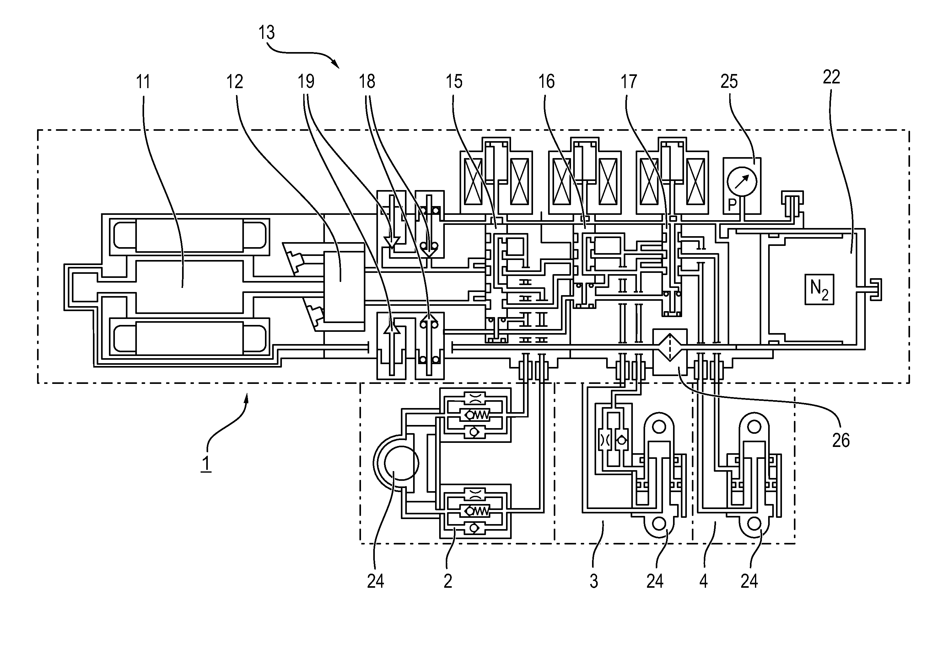
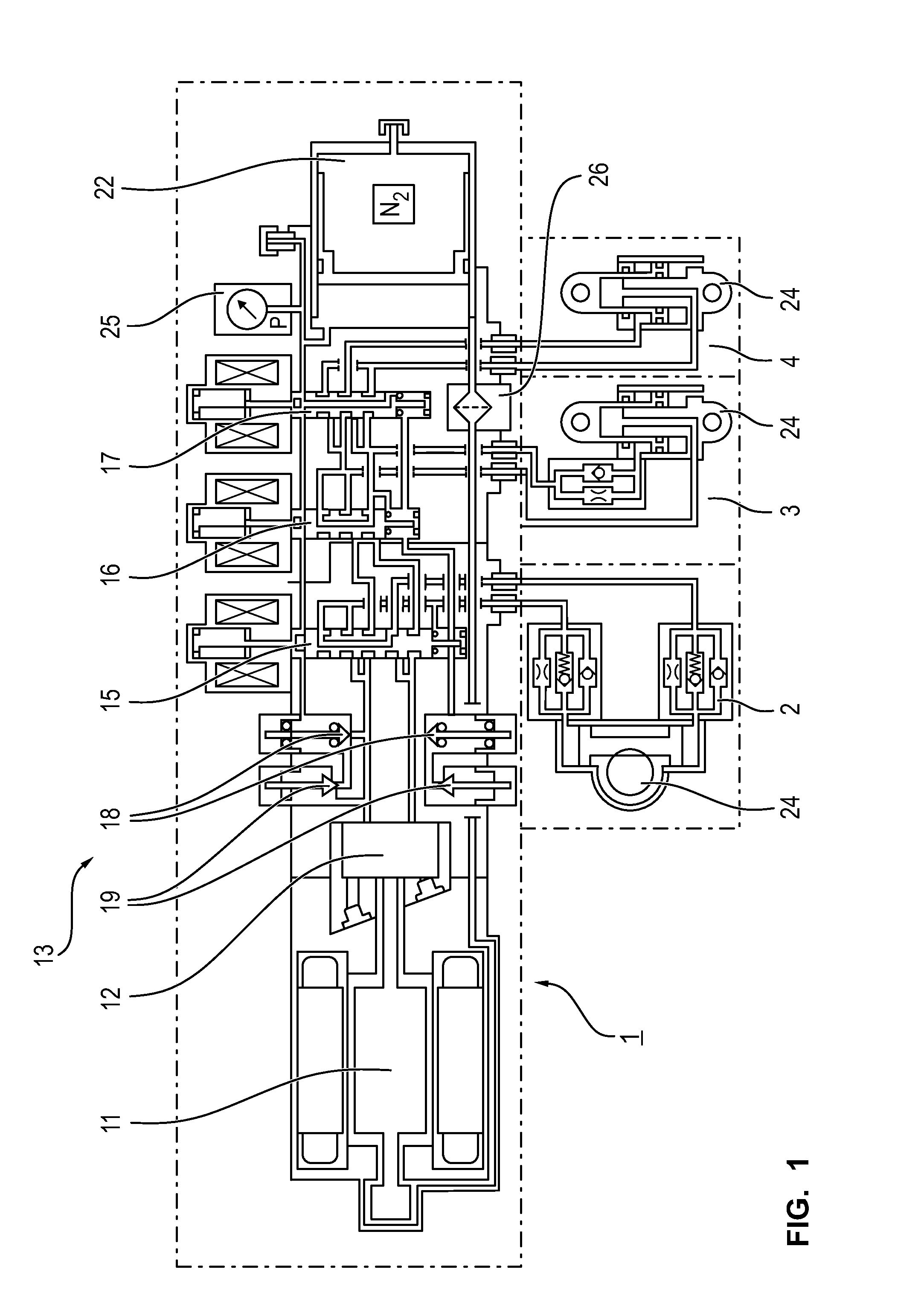
[0035]FIG. 1 shows a schematic representation of the electrohydraulic drive and control unit (EHDC unit) 1, with means provided on it for controlling different adjusting devices. In the embodiment depicted, the adjusting devices involve a landing gear control 2 with a corresponding hydraulic actuator or control motor, as the case may be, a landing gear retraction device and / or a landing gear extension device 3 with corresponding actuator, as well as a landing gear locking device 4 for locking or unlocking the landing gear, as the case may be.

[0036]The EHDC unit 1 comprises an electric motor 11, which can be designed as a regulated, brushless DC motor. A hydraulic pump 12, which can be designed as a fixed-delivery pump or an axial piston pump, as the case may be, is connected with the electric motor 11.

[0037]The operation of the hydraulic pump and, consequently, the function of the actuator or the actuators as well, is controlled or regulated by means of the rotational speed and / or t...


PUM


Abstract

The invention relates to an aircraft landing gear, particularly a front landing gear with at least one EHDC unit, which has at least one electric motor and at least one hydraulic pump, whereby at least one adjusting device is provided for the adjustment of the position of the aircraft landing gear, whereby the adjusting device comprises at least one actuator for driving the adjusting device, whereby the steering angle and/or the steering speed and/or the retraction speed and/or the extension speed and/or the end position damping and/or the position of the adjusting device can be controlled or adjusted by means of the electric motor driving the at least one actuator of the adjusting device by means of the hydraulic pump.

Description

BACKGROUND OF THE INVENTION[0001]The present invention relates to an aircraft landing gear with at least one electrohydraulic drive and control unit (EHDC unit), as well as an aircraft with such an aircraft landing gear.[0002]Aircraft landing gears with EHDC units are known from the state of the art, and are used in aircraft for the purpose of operating certain hydraulic actuators of the aircraft landing gear by means of an electric motor and a hydraulic pump.[0003]These actuators can thereby be designed for the purpose of controlling different functions of the aircraft, such as moving the control surfaces or the landing gear of the aircraft, for example. If the actuators are used in the landing gear, then the EHDC unit takes over the steering of the aircraft if the aircraft is being moved on the ground by means of the landing gear. Alternately, such EHDC units can also make it possible to control the retraction and / or the extension of the landing gear from a landing gear shaft or a...

Claims


Application Information

Patent Timeline
Patent Type & Authority Applications(United States)
IPC IPC(8): B64C25/18B64C25/50B64C25/22B64C25/26B64C25/24
CPCB64C25/18B64C25/22B64C25/26B64C25/24B64C25/50
Inventor GLAS, PETERSCHILLING, CHRISTIANSCHMELZ, KLAUS
Owner LIEBHERR AEROSPACE LINDENBERG
Why Eureka
Try Eureka