Aircraft and landing gear provided with at least one pair of shock absorbers, and a method performed by said landing gear

a technology of shock absorber and landing gear, which is applied in the direction of liquid based dampers, aircraft components, landing gear, etc., can solve the problems of reducing the performance the risk of excessively large opposing force of the shock absorber,

Active Publication Date: 2016-09-29
EUROCOPTER
View PDF14 Cites 5 Cited by
  • Summary
  • Abstract
  • Description
  • Claims
  • Application Information

AI Technical Summary

Benefits of technology

[0027]An object of the present invention is thus to propose skid landing gear provided with at least one pair of shock absorbers tending to limit the drawbacks that result from the shock absorbers being stressed during a landing mode of operation.

Problems solved by technology

Because of this high speed, the shock absorber runs the risk of exerting an excessively large opposing force, given the way the shock absorber is necessarily dimensioned to obtain results that are satisfactory during the roll mode of operation.
Consequently, the performance of the shock absorber is diminished, the opposing force obtained during the roll mode of operation ending up lower than the maximum opposing force as a result of the applied limit.

Method used


Image

  • Aircraft and landing gear provided with at least one pair of shock absorbers, and a method performed by said landing gear
  • Aircraft and landing gear provided with at least one pair of shock absorbers, and a method performed by said landing gear
  • Aircraft and landing gear provided with at least one pair of shock absorbers, and a method performed by said landing gear

Examples


first embodiment

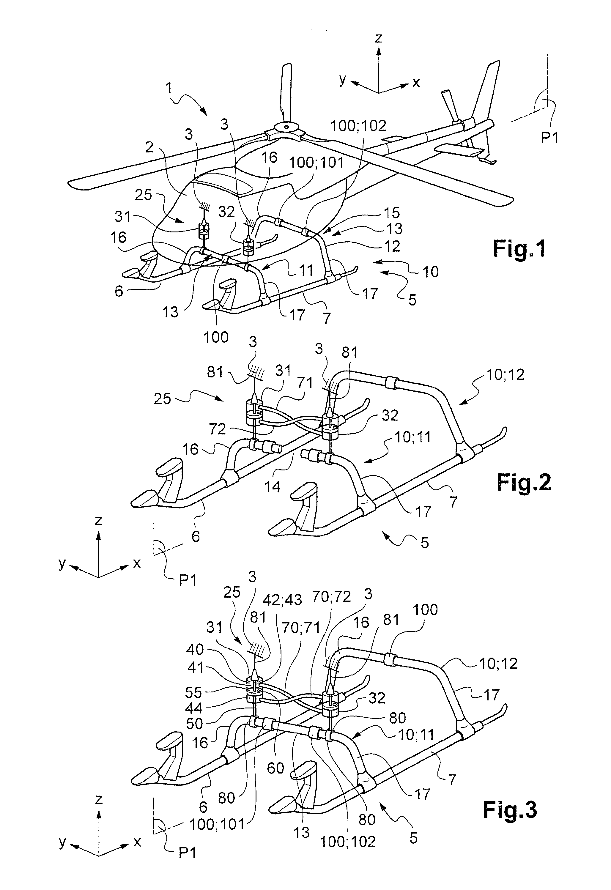
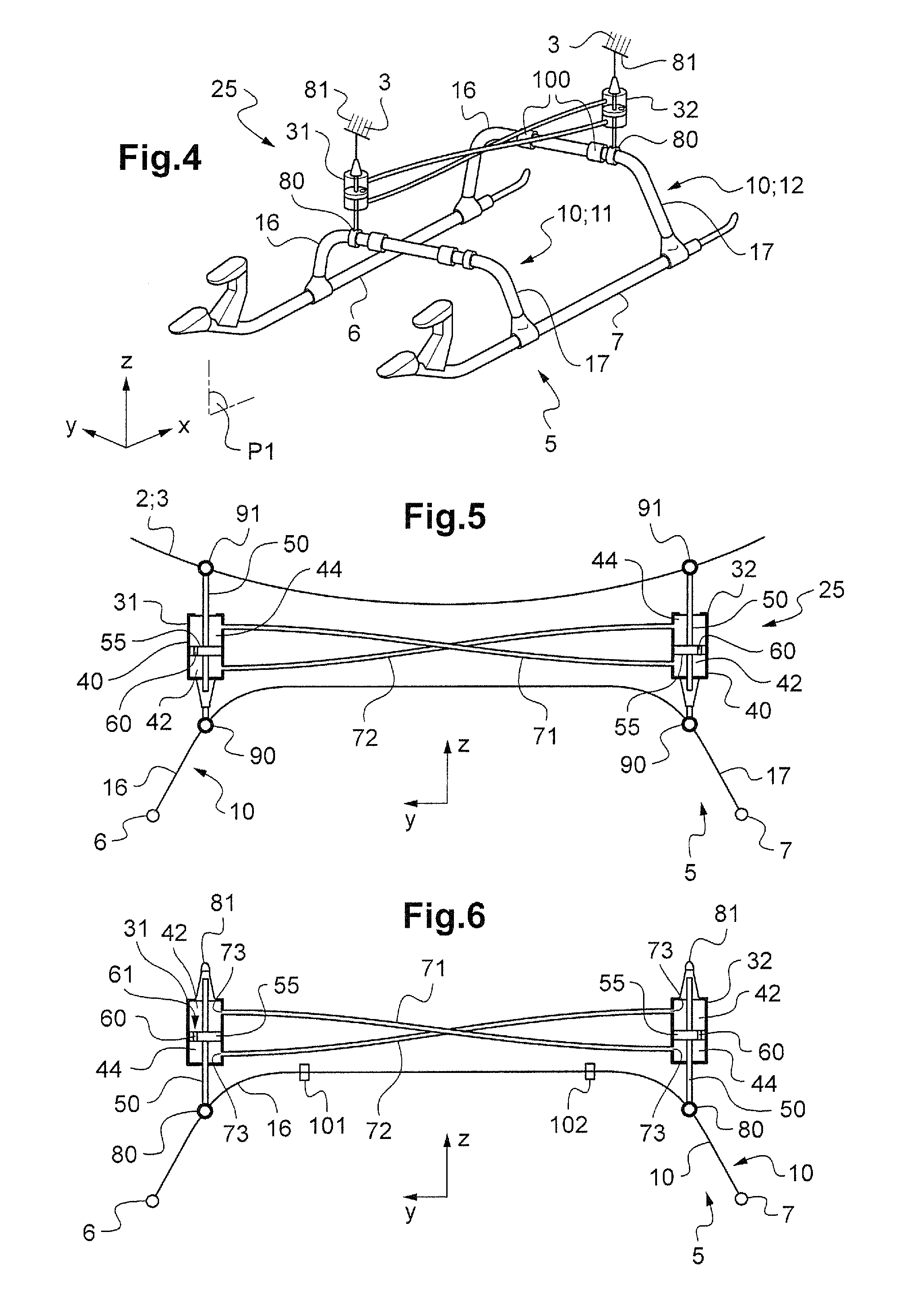
[0122]In a first embodiment shown in particular in FIG. 3, at least one shock absorber 31, 32 has a first attachment system 80 fastening the rod 50 of the shock absorber 31, 32 to a cross-member 10. Under such circumstances, a second attachment system 81 fastens the cylinder 40 of the shock absorber 31, 32 to said fuselage 2.

[0123]For example the first and / or second attachment system may comprise at least one hinge, or indeed a ball joint hinge.

second embodiment

[0124]In a second embodiment shown in particular in FIG. 5, at least one shock absorber 31, 32 has first attachment means 90 fastening the cylinder 40 of the shock absorber 31, 32 to a cross-member 10. In addition, second attachment means 91 fasten the rod 50 of the shock absorber 31, 32 to the fuselage 2.

[0125]By way of example, the first and / or second fastener means may comprise at least one hinge, or indeed a ball joint hinge.

[0126]Furthermore, and with reference to FIG. 6, the inside space 41 of each shock absorber is subdivided at least into a chamber 42 referred to as a “primary” chamber and into a chamber 44 referred to as a “secondary” chamber. The primary chamber and the secondary chamber are filled with a fluid, such as oil or a gas, for example.

[0127]The primary chamber 42 of a shock absorber possesses an inside volume 43 that decreases when the rod 50 is pushed into the cylinder 40, i.e. when the shock absorber retracts. Such retraction amounts to shortening the length o...


PUM


Abstract

Landing gear for an aircraft, the landing gear having at least one pair of shock absorbers comprising a first shock absorber and a second shock absorber, each shock absorber comprising a cylinder defining an inside space and a rod carrying a piston, the inside space being subdivided at least into a “primary” chamber and into a “secondary” chamber, the shock absorber including at least one throttling orifice putting the secondary chamber into fluid flow communication with the primary chamber. The primary chamber of the first shock absorber is connected to the secondary chamber of the second shock absorber of the pair by a first pipe, and the secondary chamber of the first shock absorber of the pair is connected to the primary chamber of the second shock absorber of the pair by a second pipe.

Description

CROSS REFERENCE TO RELATED APPLICATION[0001]This application claims priority to French patent application No. FR 15 00597 filed on Mar. 25, 2015, the disclosure of which is incorporated in its entirety by reference herein.BACKGROUND OF THE INVENTION[0002](1) Field of the Invention[0003]The present invention relates to landing gear having at least one pair of shock absorbers, and to an aircraft provided with such landing gear. The invention also relates to the method performed by the landing gear.[0004]More precisely, the invention lies in the technical field of skid landing gear for rotorcraft.[0005](2) Description of Related Art[0006]Conventionally, a rotorcraft has landing gear on which the rotorcraft stands when on the ground. More particularly, types of landing gear include landing gear referred to as “skid” landing gear, which is provided with first and second longitudinal bearing skids. The skids are for coming into contact with the ground and they are arranged on either side ...

Claims


Application Information

Patent Timeline
Patent Type & Authority Applications(United States)
IPC IPC(8): B64C25/52B64C25/60F16F9/20B64C25/58
CPCB64C25/52B64C25/58B64C2025/325F16F9/20B64C25/60
Inventor PRUD'HOMME-LACROIX, PIERREGARCIN, PATRICE
Owner EUROCOPTER
Why Eureka
Try Eureka