Interior aircraft LED light unit and method of calibrating an interior aircraft LED light unit

a led light unit and led light technology, applied in the direction of aircraft indicators, structural/machine measurement, lighting and heating apparatus, etc., can solve the problems of large deviation range, insufficient accuracy, and inability to meet the requirements of production time, etc., to achieve accurate results

Inactive Publication Date: 2016-09-29
GOODRICH LIGHTING SYST
View PDF4 Cites 2 Cited by
  • Summary
  • Abstract
  • Description
  • Claims
  • Application Information

AI Technical Summary

Benefits of technology

[0026]According to a further embodiment, the step of providing the distal side of the lens cover with the pattern of dots comprises the steps of determining a deviation of the initial lighting performance from a desired lighting performance and selecti

Problems solved by technology

However, with LEDs often having large production tolerances and, thus, the interior LED light units potentially having a large range of deviations from a desired lighting performance, countermeasures with respect to such deviations are carried out during production of the light units.
However, such countermeasures are involving, need substantial production time and/or are not fully satisfactory in terms of accuracy.
Such in

Method used


Image

  • Interior aircraft LED light unit and method of calibrating an interior aircraft LED light unit
  • Interior aircraft LED light unit and method of calibrating an interior aircraft LED light unit
  • Interior aircraft LED light unit and method of calibrating an interior aircraft LED light unit

Examples


Embodiment Construction

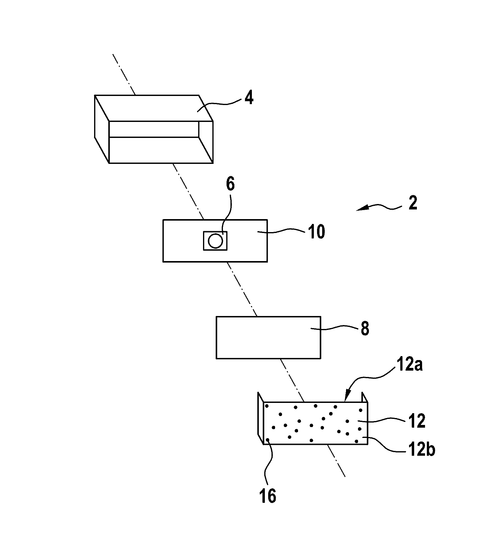
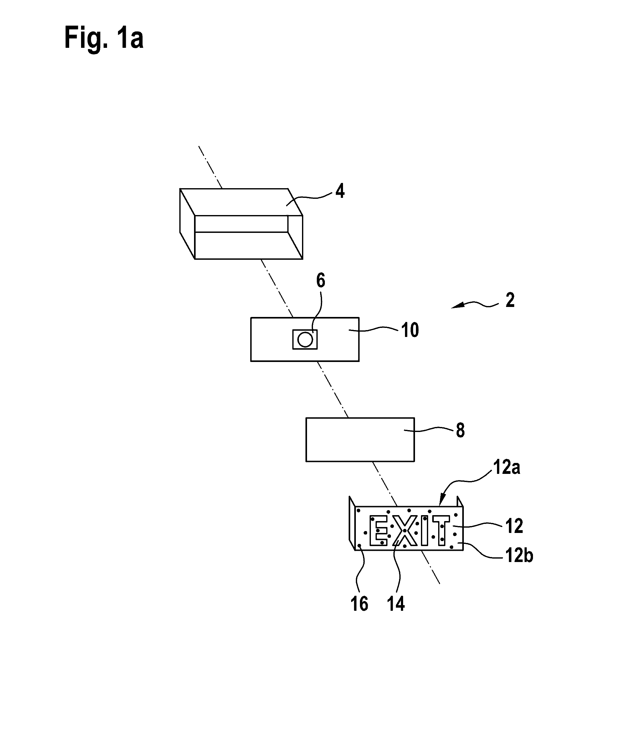
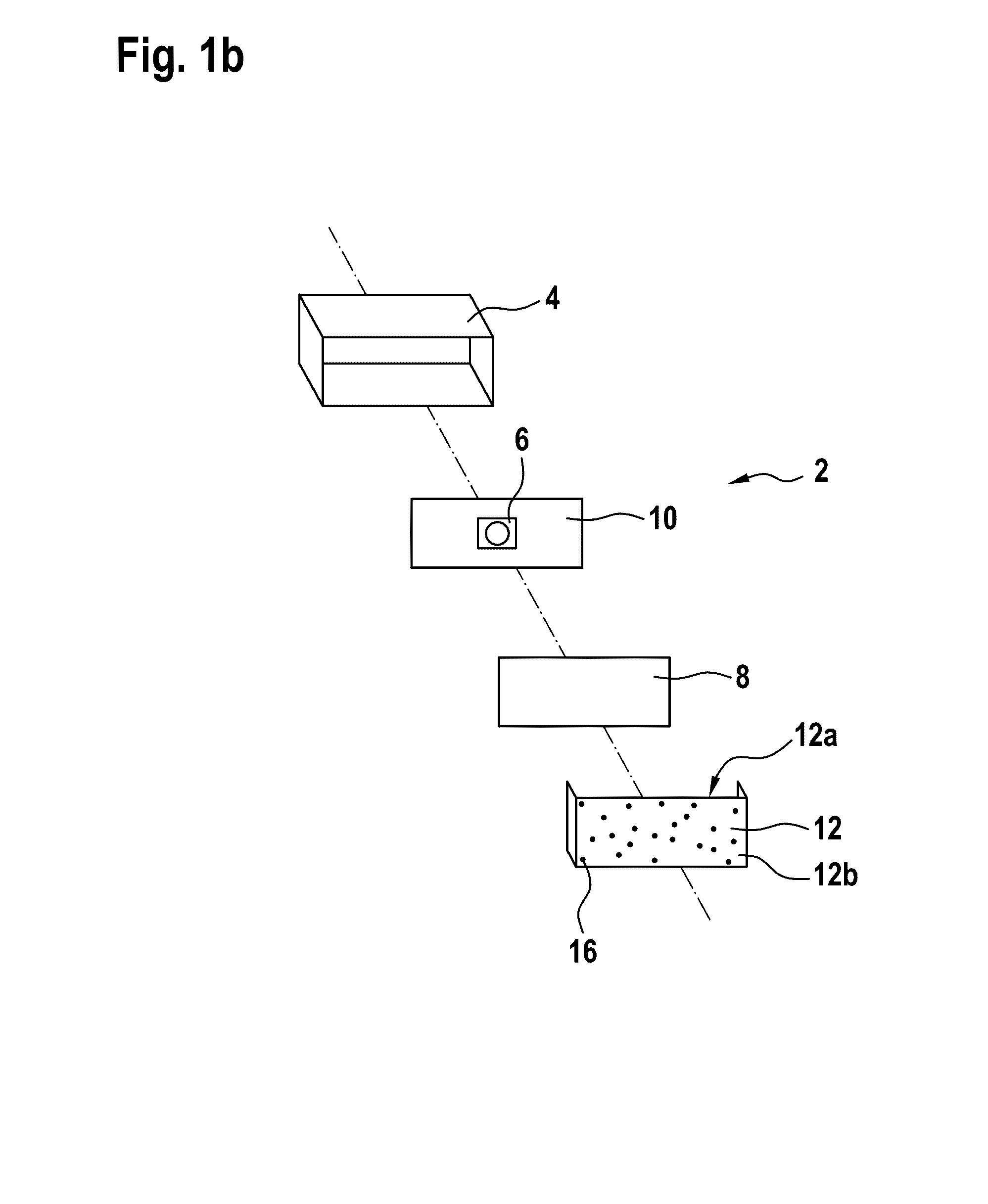
[0030]FIG. 1a shows an interior aircraft LED light unit 2 in accordance with an exemplary embodiment of the invention. The interior aircraft LED light unit 2 is shown in an exploded view, such that the individual elements can be seen better.

[0031]The interior aircraft LED light unit 2 comprises a housing 4, a mounting plate 10, to which an LED 6 is mounted, a brightness filter 8, and a lens cover 12. The housing 4 is a generally cuboid structure in the exemplary embodiment of FIG. 1a. The mounting plate 10 has a generally planar front surface, and the LED 6 is mounted to substantially the center of the mounting plate 10. When assembled, the mounting plate 10 is positioned towards the back of the housing 4. The brightness filter 8 is a generally planar structure, whose size is fitted to match the size of the lens cover 12 and which is positioned adjacent to the lens cover 12 in the assembled state.

[0032]The lens cover 12 has a generally flat front portion and two side portions, with ...


PUM


Abstract

An interior aircraft LED light unit includes at least one LED and a lens cover arranged over the at least one LED, the lens cover having a proximal side facing towards the at least one LED and a distal side forming an outside portion of the interior aircraft LED light unit, with the lens cover being made from a lens cover material exhibiting material-specific light transfer properties. The lens cover comprises a pattern of dots on the distal side, with each of the pattern of dots locally altering the material-specific light transfer properties of the lens cover.

Description

FOREIGN PRIORITY[0001]This application claims priority to European Patent Application No. 15 161 048.2 filed on Mar. 26, 2015, the entire contents of which is incorporated herein by reference.TECHNICAL FIELD[0002]The present invention relates to interior aircraft lighting. In particular, it relates to interior aircraft light units employing LED technology.BACKGROUND OF THE INVENTION[0003]Almost all modern aircraft, in particular commercial passenger aircraft, have interior lighting. The interior light units of an aircraft serve a variety of different purposes. Cabin illumination light units are provided for a general illumination of the aircraft cabin, allowing the passengers and crew to be aware of their surroundings and to walk around the cabin. Signalling lights, such as exit sign light units, are provided for conveying information to the passengers and crew, such as safety-critical information about the positions of the emergency exits of the aircraft. Further, targeted lighting...

Claims


Application Information

Patent Timeline
IPC IPC(8): B64D11/00F21V3/04B60Q3/02
CPCB64D11/00B60Q3/025B64D2011/0038B60Q3/0253F21V3/049B60Q3/0256G09F13/04B64D2011/0053B64D2045/007B64D2203/00G09F2013/222B60Q3/43B60Q3/44B60Q3/46F21Y2115/10G09F13/044G09F2013/05H01L33/44G01M11/0285
Inventor SCHOEN, CHRISTIANVOELKEL, STEFAN
Owner GOODRICH LIGHTING SYST
Why Eureka
Try Eureka