Shock absorber

a technology of shock absorber and shock absorber, which is applied in the direction of shock absorber, liquid based damper, vibration damper, etc., can solve the problem of difficulty in reducing vibration at a frequency equal to or more than the upper limit, and achieve the effect of improving the ride comfort in the vehicl

Inactive Publication Date: 2016-09-29
KYB CORP
View PDF6 Cites 15 Cited by
  • Summary
  • Abstract
  • Description
  • Claims
  • Application Information

AI Technical Summary

Benefits of technology

[0008]However, the frequency of the vehicle body vibration that determines ride comfort in the vehicle is a higher frequency than the frequency band that allows vibration damping. A conventional shock absorber does not allow reducing the vibration at this high frequency, and thus it is requested to further improve the ride comfort in the vehicle.
[0009]An object of the present invention is to provide a shock absorber that allows improving the ride comfort in the vehicle.

Problems solved by technology

Accordingly, it is difficult to reduce the vibration at a frequency equal to or more than the upper limit.

Method used


Image

  • Shock absorber
  • Shock absorber
  • Shock absorber

Examples


Embodiment Construction

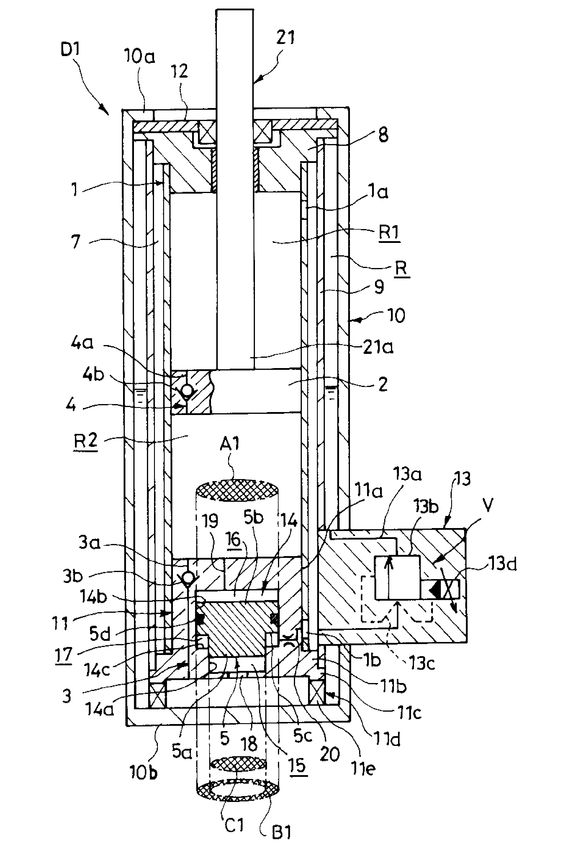
[0031]Hereinafter, a shock absorber according to an embodiment of the present invention will be described with reference to the drawings. In the following, the upper side is described as “above” and the lower side is described as “below” in the respective drawings other than the attenuation characteristic diagram.

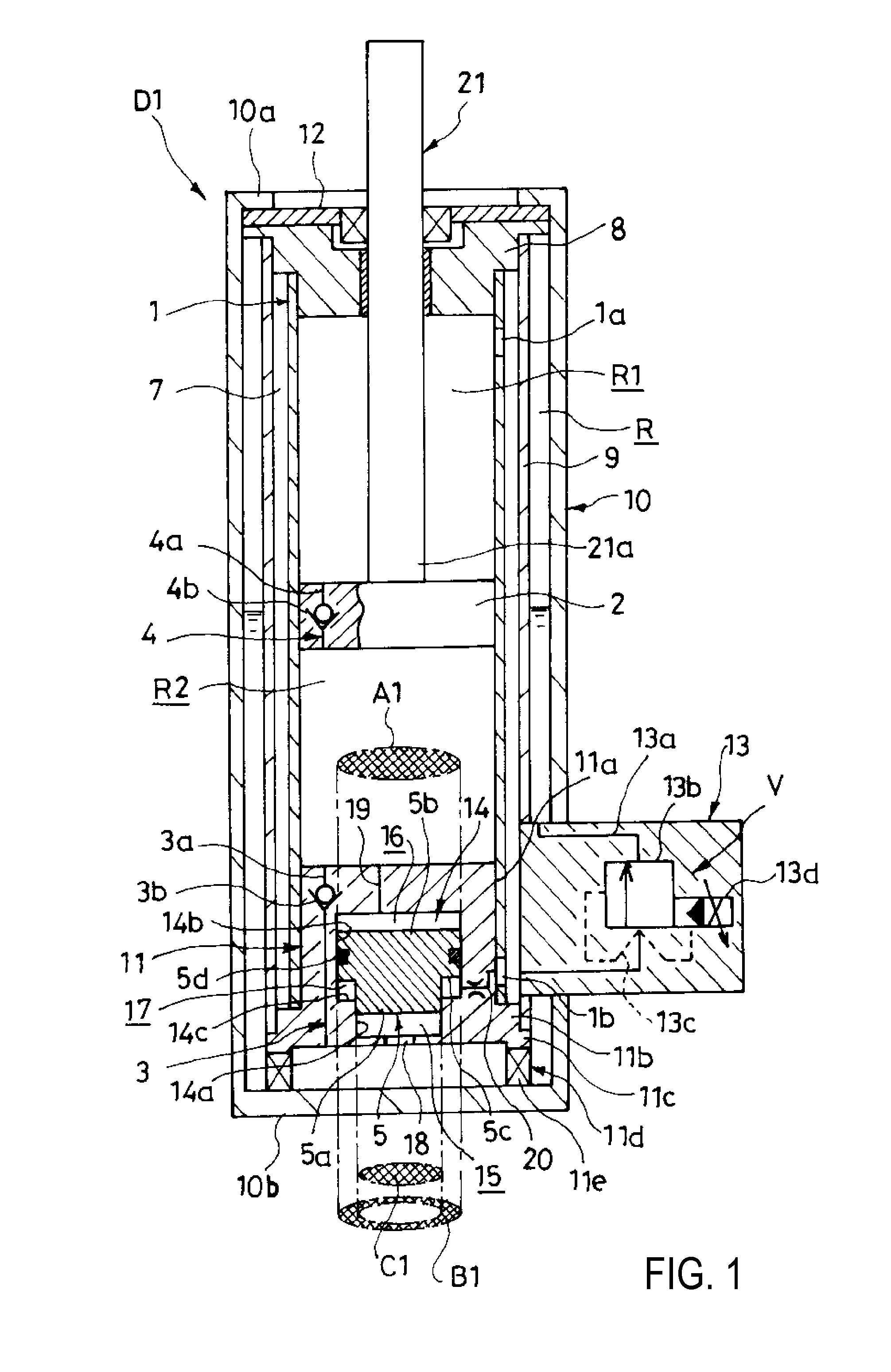
[0032]As illustrated in FIG. 1, a shock absorber D1 includes a cylinder 1, a piston 2, a reservoir R, a suction passage 3, a rectifying passage 4, a damping force variable valve V, a bottom member 11, and a free piston 5.

[0033]The piston 2 is slidably inserted into the cylinder 1, and defines the expansion side chamber R1 and the pressure side chamber R2 inside the cylinder 1. The suction passage 3 allows only a flow of liquid from the reservoir R toward the pressure side chamber R2. The rectifying passage 4 allows only a flow of liquid from the pressure side chamber R2 toward the expansion side chamber R1. The damping force variable valve V is a damping force adjusting uni...


PUM


Abstract

Shock absorber including a suction passage allowing flow only from a reservoir towards a pressure side chamber, a rectifying passage allowing flow only from the pressure side chamber towards an expansion side chamber, and a damping force variable valve allowing flow only from the expansion side chamber towards the reservoir. A large pressure-side pressure chamber communicating with the pressure side chamber, and an outer peripheral expansion-side pressure chamber communicating with the expansion side chamber sandwich a free piston slidably moving within a bottom housing forming a pressure chamber. Because a pressure-side pressure-receiving area of the free piston is larger than an expansion-side pressure-receiving area in a contraction operation in which a piston moves downward, the free piston can move downward even in a uniflow-type shock absorber in which pressure in the expansion side and pressure side chambers become equal whereby damping force can be reduced during an input of high-frequency vibration.

Description

TECHNICAL FIELD[0001]The present invention relates to improvement of a shock absorber.BACKGROUND ART[0002]A shock absorber includes a cylinder, a piston, a piston rod, an expansion side chamber, a pressure side chamber, an intermediate pipe, an outer pipe, a suction passage, a rectifying passage, and a damping force variable valve. The piston is slidably inserted into the cylinder. The piston rod is inserted into the cylinder to couple to the piston. The expansion side chamber and the pressure side chamber are defined by the piston. The intermediate pipe covers the outer periphery of the cylinder to form a discharge passage with the cylinder. The outer pipe covers the outer periphery of the intermediate pipe to form a reservoir with the intermediate pipe. The suction passage allows only a flow of operation oil from the reservoir toward the pressure side chamber. The rectifying passage is disposed in the piston, and allows only a flow of operation oil from the pressure side chamber t...

Claims


Application Information

Patent Timeline
Patent Type & Authority Applications(United States)
IPC IPC(8): F16F9/516F16F9/18F16F9/06F16F9/34F16F9/512
CPCF16F9/5165F16F9/34F16F9/187F16F9/061F16F9/5126
Inventor TERAOKA, TAKASHIMASAMURA, TATSUYA
Owner KYB CORP
Why Eureka
Try Eureka