Electromagnetic Suspension Device

Inactive Publication Date: 2009-01-29
KYB CORP +1
View PDF7 Cites 8 Cited by
  • Summary
  • Abstract
  • Description
  • Claims
  • Application Information

AI Technical Summary

Benefits of technology

[0014]Thus, according to the electromagnetic suspension device of the present invention, the d- and q-phase electric currents can be controlled to respective electric current target values and it is possible to gener

Problems solved by technology

However, in a dynamic state in the control using the above dq conversion, not only the d-phase electric current and the q-phase electric current interfere with each other but also, under the influence of induced electromotive force, there occurs a deviation between the target values of the electric currents in th

Method used


Image

  • Electromagnetic Suspension Device
  • Electromagnetic Suspension Device
  • Electromagnetic Suspension Device

Examples


Example

[0020]The present invention will be described hereunder by way of embodiments thereof illustrated in the drawings.

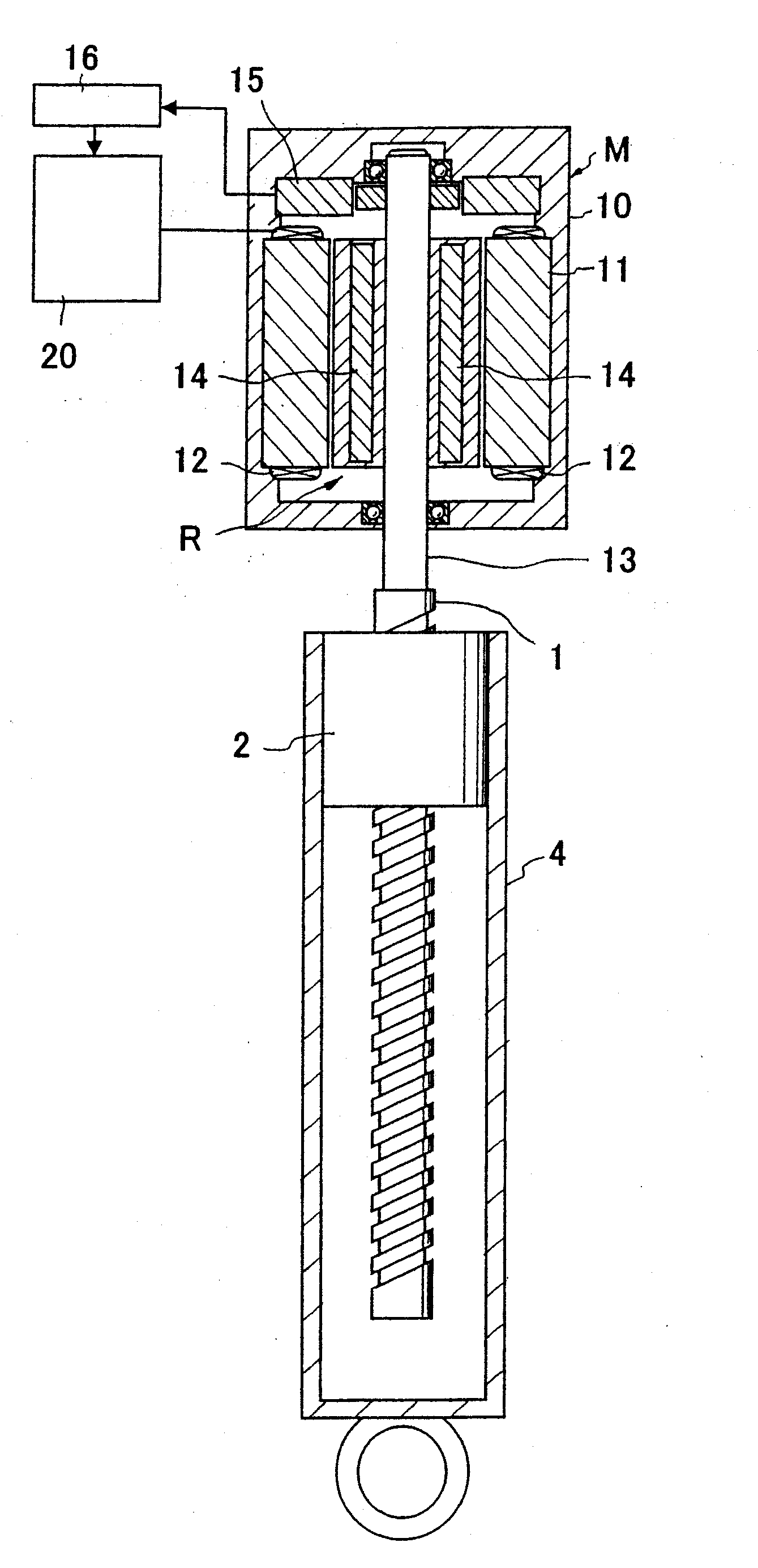
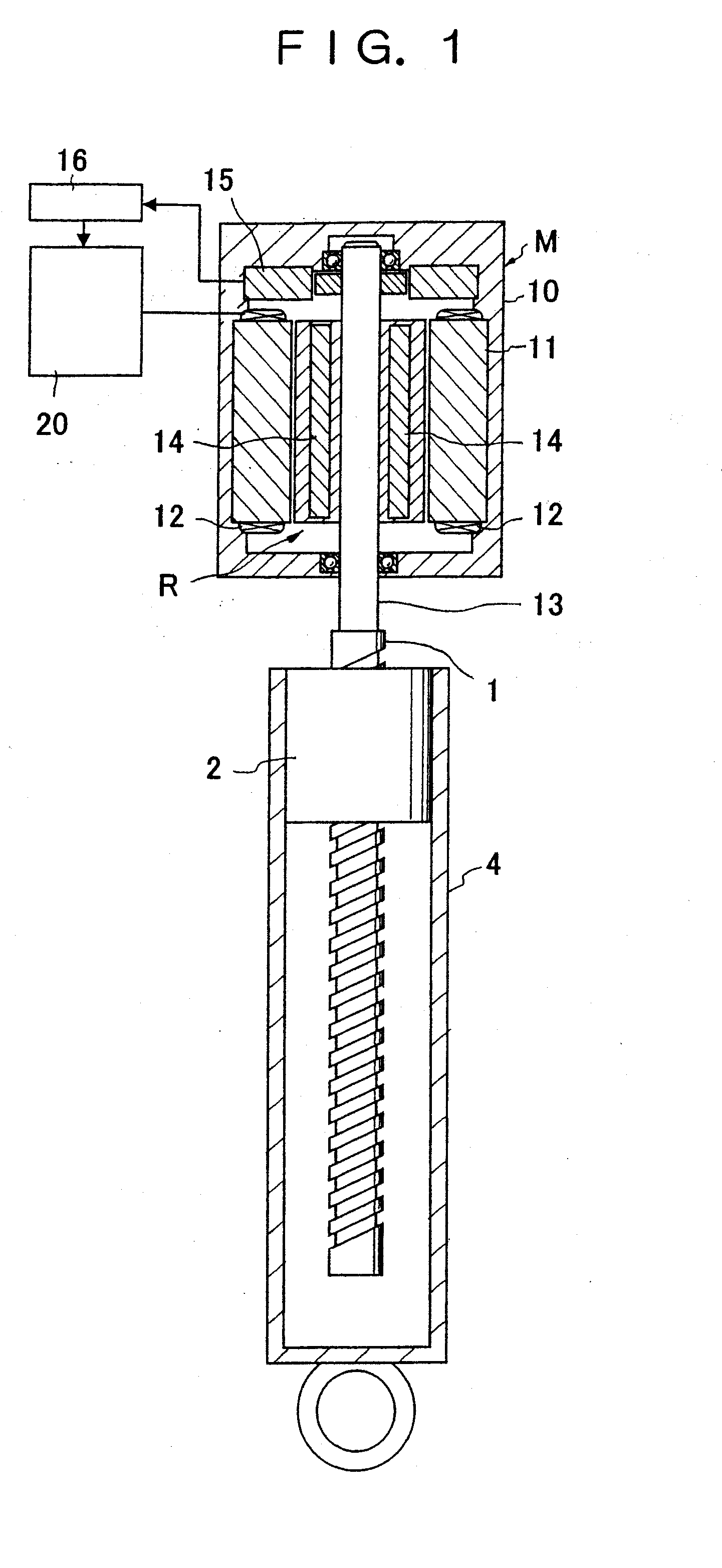
[0021]As shown in FIG. 1, an electromagnetic suspension device according to an embodiment of the present invention is made up of a screw shaft 1 as one member, a ball screw nut 2 adapted to perform a relative motion with respect to the screw shaft 1, and a motor M.

[0022]More specifically, the screw shaft 1 is threadedly engaged with the ball screw nut 2 rotatably and an upper end in FIG. 1 of the screw shaft 1 is connected to a rotor R of the motor M. On the other hand, the ball screw nut 2 is fixed to an upper end of a tube 4 into which the screw shaft 1 is inserted and the ball screw nut 2 can be connected through the tube 4 to one of a sprung member and an unsprung member of a vehicle.

[0023]The screw shaft 1 is connected rotatably to the other of the vehicular sprung and unsprung members. More specifically, the screw shaft 1 is journaled to a ball bearing provided in ...


PUM


Abstract

In an electromagnetic suspension device comprising one member (1), the other member (2) adapted to perform a relative motion with respect to the one member (1), and a motor (M) capable of at least suppressing the relative motion, and wherein electric current values id and iq of d and q phases are determined using dq conversion from electric currents iv and iu flowing in the motor (M) and an electrical angle θ of a rotor, and the motor (M) is controlled on the basis of both d-phase voltage command value Vd1 and q-phase voltage command value Vq1, the improvement characterized by further comprising correction means (23) for correcting the d-phase voltage command value Vd1 on the basis of both q-phase electric current iq and electrical angular velocity ω of the rotor and correcting the q-phase voltage command value Vq1 on the basis of both d-phase electric current id and electrical angular velocity ω of the rotor.

Description

FIELD OF ART[0001]The present invention relates to an improvement of an electromagnetic suspension device most suitable for vehicles.BACKGROUND ART[0002]For example, in Japanese Patent Laid-Open Publication No. 2003-104025 there is disclosed an electromagnetic suspension device wherein a linear motor is comprised of a tube connected to either a sprung member or an unsprung member of a vehicle, a rod connected to either the sprung member or the unsprung member and inserted into the tube, plural permanent magnets arranged axially on the outer periphery of the rod, and plural windings disposed on the inner periphery of the tube in opposition to the permanent magnets, an electromagnetic force of the linear motor being utilized as a load (control force) for suppressing an axial relative motion between the rod and the tube.[0003]As to control of a motor in an electromagnetic suspension device, as is disclosed in Japanese Patent Laid-Open Publication No. Hei 6 (1994)-153569, there is perfo...

Claims


Application Information

Patent Timeline
IPC IPC(8): H02P21/05B60G17/00F16F15/03H02P21/00H02P27/04H02P27/08
CPCB60G17/0157B60G2202/42B60G2204/4193F16F15/03H02P25/06H02P21/0035H02P21/0089H02P21/06F16F2232/04H02P21/00H02P21/22H02P25/062
Inventor KUBOTA, TOMOOINOUE, HIROFUMI
Owner KYB CORP
Why Eureka
Try Eureka