

Image generation apparatus and image generation method
a technology of image generation and image, applied in the field of image generation apparatus and image generation method, can solve the problems of lack of immersion or inability of users to concentrate their attention on the screen image of the display unit, and achieve the effect of reducing the time after image generation
- Summary
- Abstract
- Description
- Claims
- Application Information
AI Technical Summary
Benefits of technology
Problems solved by technology
Method used
Image


Examples
first embodiment
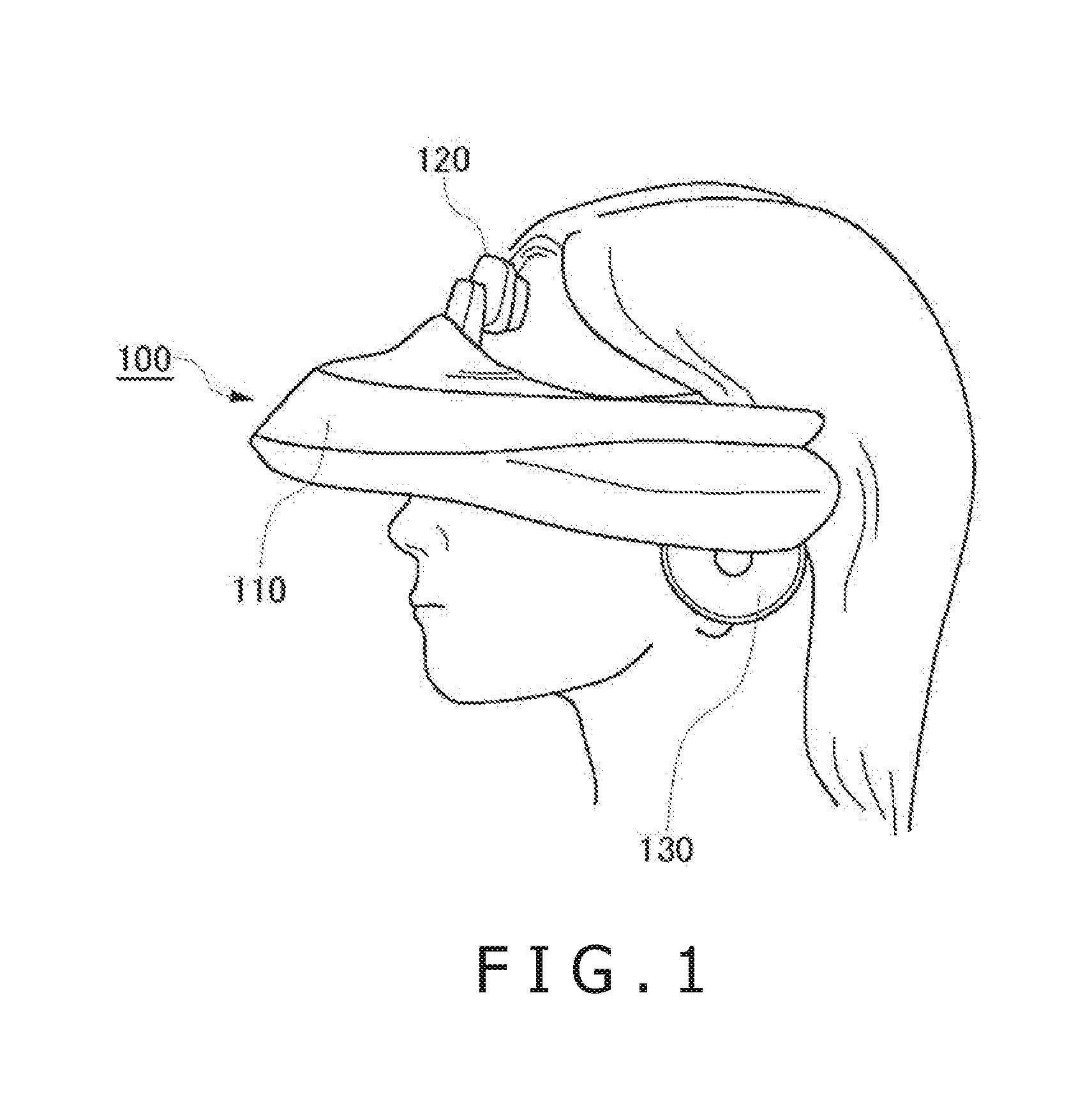
[0027]FIG. 1 is an appearance view of a head-mounted display unit 100. The head-mounted display unit 100 includes a main body unit 110, a front head portion contact unit 120, and side head portion contact portions 130.
[0028]The head-mounted display unit 100 is a display apparatus which is mounted on the head of a user such that the user appreciates a still picture or a moving picture displayed on a display unit and listens to sound, music or the like outputted from a headphone.
[0029]Position information of a user can be measured by a position sensor such as a GPS (Global Positioning System) built in or externally mounted on the head-mounted display unit 100. Further, posture information such as a rotational angle or an inclination of the head of the user, who wears the head-mounted display unit 100, can be measured by a posture sensor built in or externally mounted on the head-mounted display unit 100.
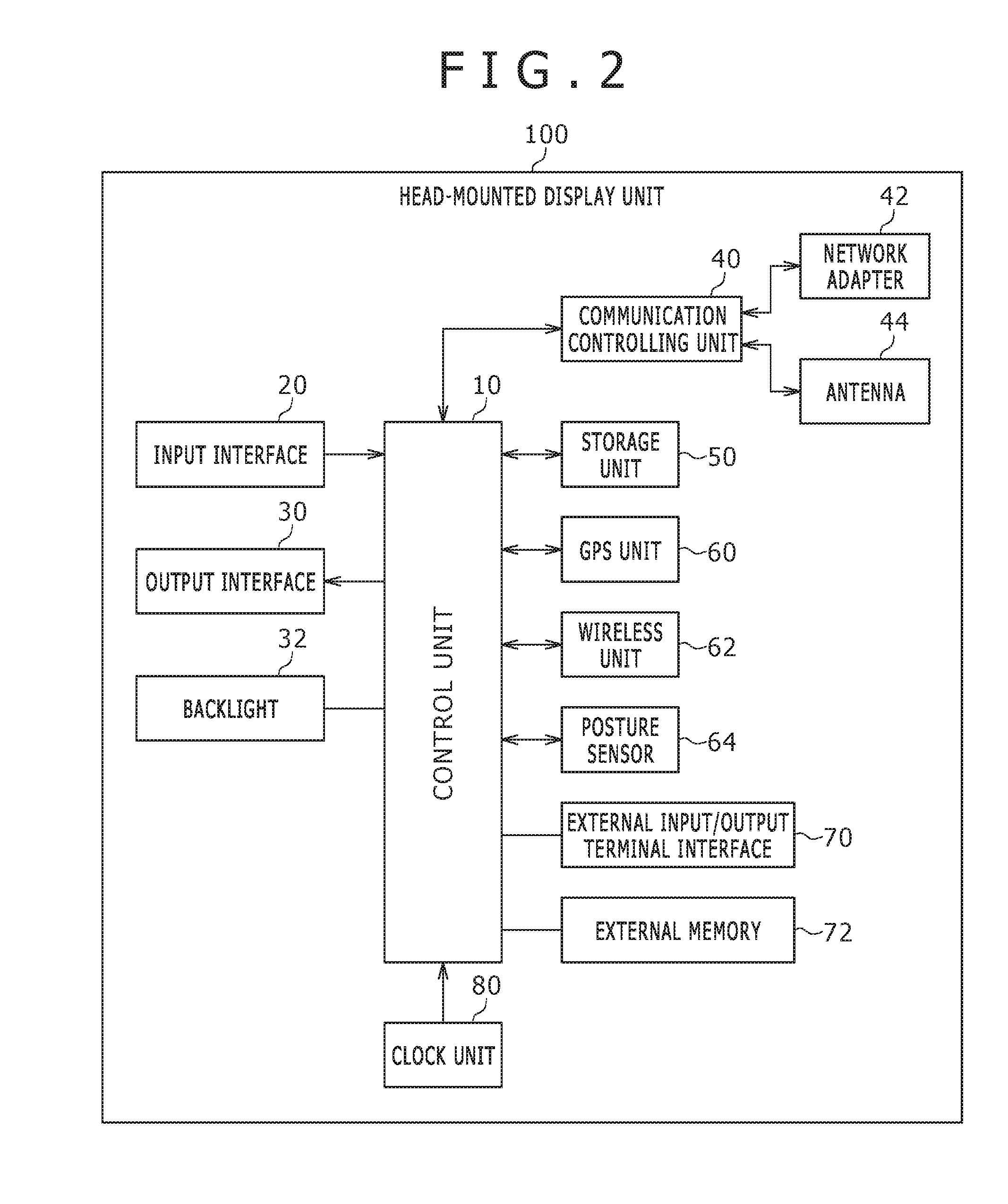
[0030]The main body unit 110 includes the display unit, a position information acq...
modification 1
(Modification 1)
[0126]A modification to the correction process of the first embodiment is described with reference to FIGS. 12 and 13. FIG. 12 is a view illustrating, for comparison, the image correction process of the first embodiment. As depicted in the figure, at time t1, the panorama image generation apparatus 700 receives a position p1 and a rotation q1 of the head-mounted display unit 100 and starts rendering. At time t2, the panorama image generation apparatus 700 performs a correction process for a generated image using the latest position p2 and the rotation q2 of the head-mounted display unit 100. If it is assumed that the frame rate of the panel of the head-mounted display unit 100 is 30 frames / second, the panorama image generation apparatus 700 generates a frame at 30 frames / second and performs the correction process and then provides an image after the correction to the head-mounted display unit 100. It is to be noted that the correction process may be performed on the ...
modification 2
(Modification 2)
[0130]Although the coordinate transformation expression (x′, y′, z′, 1)=(x, y, z, 1)×W×V×B×H×D×P includes multiplication of the tracking reference transformation matrix B and the HMD position rotation matrix H, this calculation can be simplified. A matrix of a result when the tracking reference transformation matrix B and the HMD position rotation matrix H are multiplied is referred to as normalized HMD matrix N. The tracking reference transformation matrix B can be determined as an inverse matrix of the HMD position rotation matrix H generated from the sensor information when the head-mounted display unit 100 is placed at the reference position p0 and the reference rotation q0. Further, the HMD position rotation matrix H (p, q) is generated from the translation matrix T and the rotation matrix R using the position p and the rotation q acquired from the sensors upon starting of the rendering. Therefore, where an inverse matrix is represented by Inv (·), the normalize...
PUM
 Abstract
Description
Claims
Application Information