

Interactive projector and method of controlling interactive projector
a projector and interactive technology, applied in the field of interactive projectors, can solve problems such as the inability to obtain appropriate detection results in some cases
- Summary
- Abstract
- Description
- Claims
- Application Information
AI Technical Summary
Benefits of technology
Problems solved by technology
Method used
Image

Examples
first embodiment
B. Position Detection Section
Template Size is Varied in Accordance with Local Magnification
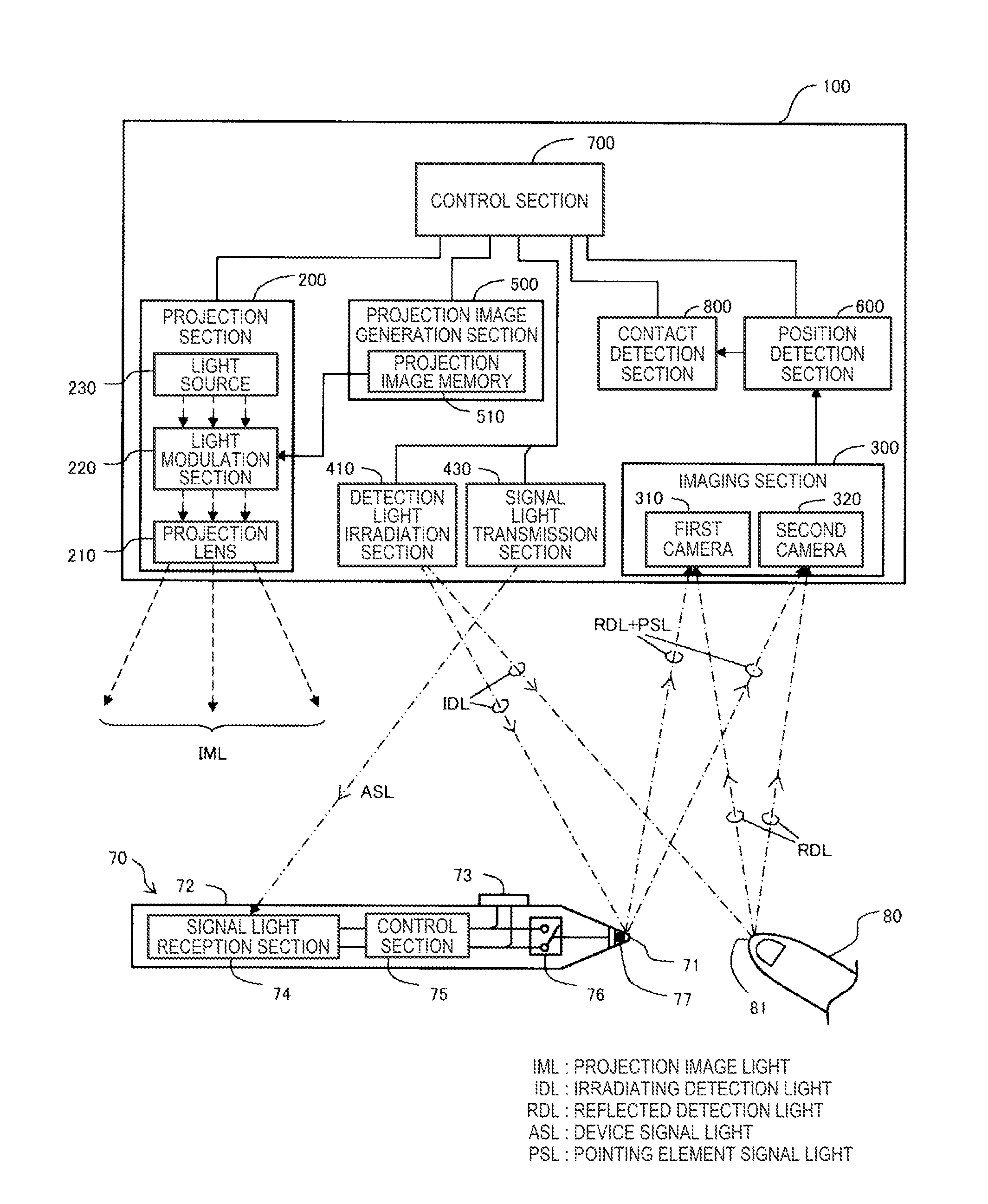
[0084]FIG. 5 is a block diagram showing a schematic configuration of the position detection section 600 (FIG. 3). The position detection section 300 is provided with a correlation value calculation section 620, a correlation value map generation section 640, a pointing element detection section 660, and a three-dimensional position calculation section 680. The correlation value calculation section 620 is provided with a plurality of template sets (here, three template sets S1 through S3). Each of the template sets is provided with a plurality of types of template images (in the template set S1 shown in FIG. 5, three types of template images T11 through T13). Hereinafter, in the case in which the three template sets S1 through S3 are not discriminated from each other, the template sets are also referred to as template sets S. Further, in the case in which the three types of template images T11 ...
second embodiment
C. Position Detection Section
Image Resolution is Varied in Accordance with Local Magnification
[0105]FIG. 12 is a block diagram showing a configuration of a position detection section 600A according to a second embodiment of the invention. The position detection section 600A according to the second embodiment is provided with a correlation value calculation section 620A instead of the correlation value calculation section 620 in the position detection section 600 according to the first embodiment. The correlation value calculation section 620A is provided with a plurality of template images (here, three template images T1 through T3). The template images T1 through T3 according to the present embodiment are the same as the template images T21 through T23 (FIGS. 8A through 8C) according to the first embodiment, and each have the size of 13×13 pixels. In the present embodiment, the template images T1 through T3 are each generated using an image obtained by the imaging section 300 imagi...
third embodiment
D. Position Detection Section
Plurality of Correlation Values are Added with Weight Corresponding to Local Magnification
[0115]A correlation value calculation section of an interactive projector according to the third embodiment is provided with the three template images T1 through T3 similarly to the correlation value calculation section 620A according to the second embodiment. The template images T1 through T3 according to the present embodiment are images having similar figures to those of the template images according to the second embodiment, and each have the size of 15×15 pixels. In the present embodiment, the template images T1 through T3 are each generated using an image obtained by the imaging section 300 imaging the state in which an area of the screen surface SS corresponding to the small area MR3 of the taken image M0 is pointed by a predetermined finger. In other words, the size of the finger included in the template image T corresponds to an average size of the non-ligh...
PUM
 Abstract
Description
Claims
Application Information