System to control camera triggering and visualize aerial imaging missions

a technology of camera triggering and visualization, applied in the field of real-time aerial imaging mission visualization, can solve the problems of difficult to ensure the coverage of the area of interest, the amount of image overlap is difficult to ensure, and the manned and unmanned aircraft operate at much lower altitudes. , to achieve the effect of minimizing the variability of offset of the camera, the interface is easy to achiev

Active Publication Date: 2016-09-29
FIELD OF VIEW LLC
View PDF10 Cites 16 Cited by
  • Summary
  • Abstract
  • Description
  • Claims
  • Application Information

AI Technical Summary

Benefits of technology

[0009]The mission visualization system can perform direct georeferencing calculations to project the captured image's footprint or the captured image onto a virtual representation of Earth's surface using the image-associated geographic position and attitude data provided by the control and data management device. The visualization can be displayed in real-time over a virtual representation of Earth's surface to allow the operator of a manned or unmanned aircraft to confirm, during a mission, that...

Problems solved by technology

However, manned and unmanned aircraft both operate at much lower altitudes than satellites and cannot capture as large of an area in one image.
The amount of image overlap and coverage over the area of interest can be difficult to ensure, especially during a mission.
Lack of sufficient coverage typically is not recognized until after an attempt to process the imagery into a mosaic, a lengthy process that, depending on the resolution and number of images, can take many hours.
If lack of coverage, non-sufficient overlap, or a bad image is discovered, the operator has to re-do the mission to collect the required imagery.
This mission can be delayed due to weather or other considerations, or it can interfere with the scheduling of...

Method used


Image

  • System to control camera triggering and visualize aerial imaging missions
  • System to control camera triggering and visualize aerial imaging missions
  • System to control camera triggering and visualize aerial imaging missions

Examples


Embodiment Construction

[0019]Various embodiments will be described in detail with reference to the drawings, wherein like reference numerals represent like parts and assemblies throughout the several views. Reference to various embodiments does not limit the scope of the claims attached hereto. Additionally, any examples set forth in this specification are not intended to be limiting and merely set forth some of the many possible embodiments for the appended claims. It is understood that various omissions and substitutions of equivalents are contemplated as circumstances may suggest or render expedient, but these are intended to cover application or embodiments without departing from the spirit or scope of the claims attached hereto. Also, it is to be understood that the phraseology and terminology used herein are for the purpose of description and should not be regarded as limiting.

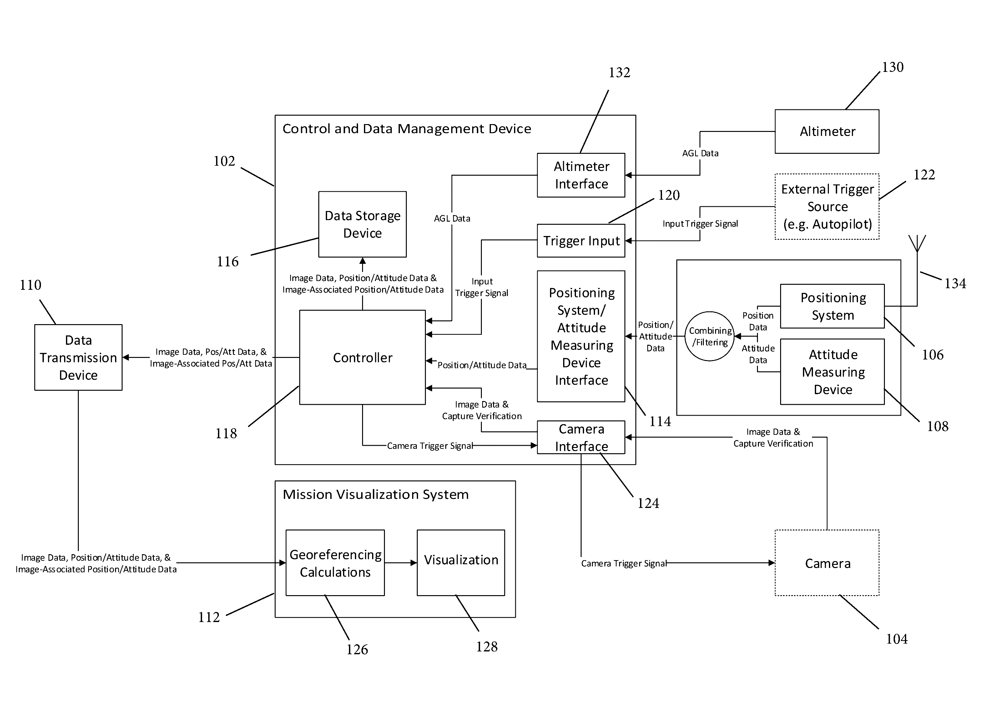
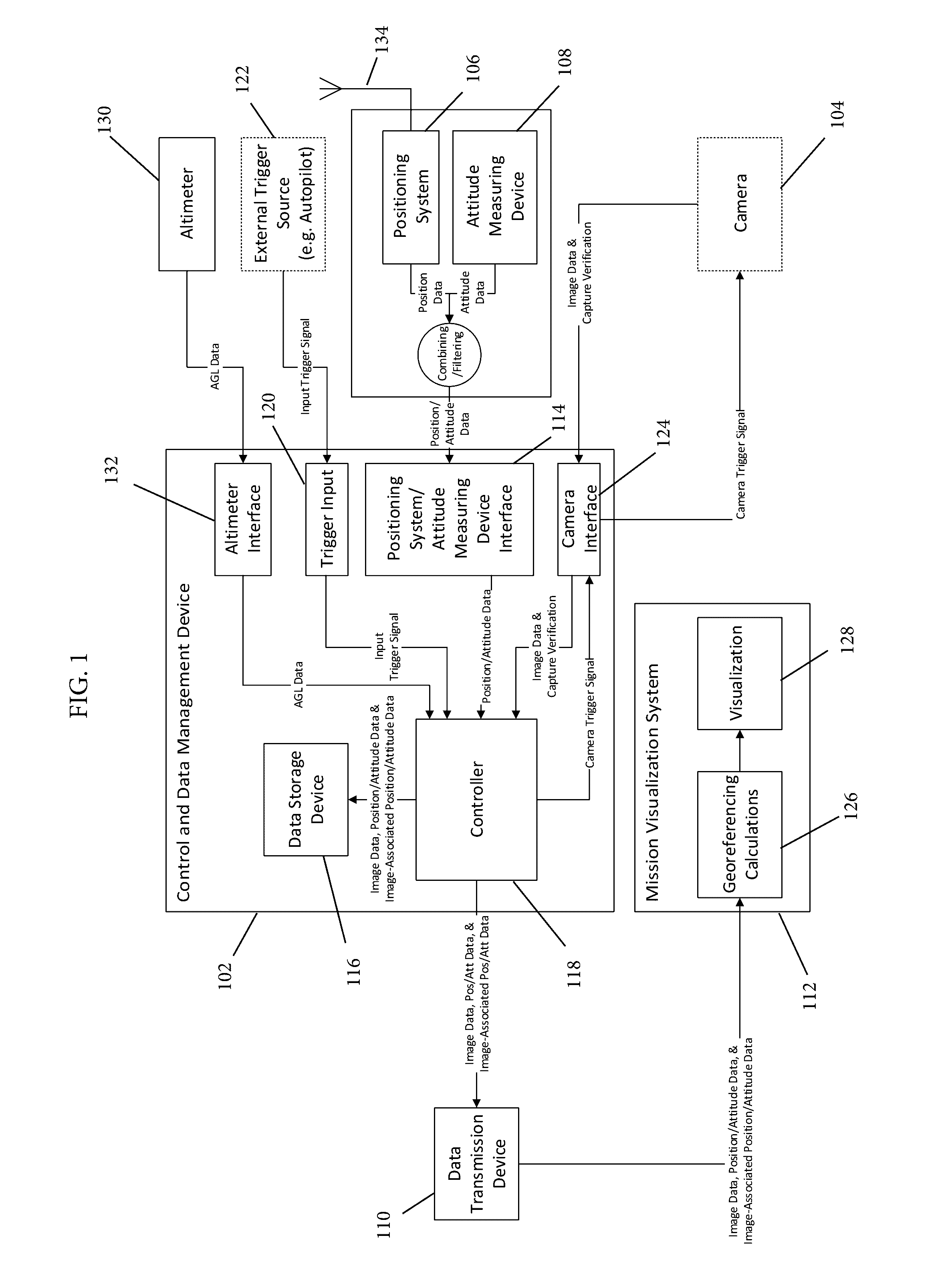
[0020]In a preferred embodiment, as illustrated in FIG. 1, the disclosed aerial imaging system includes: a control and data ...


PUM


Abstract

A camera triggering and aerial imaging mission visualization system. More specifically, a system that controls camera triggering, manages data from a positioning system and an attitude measuring device, and provides real-time image coverage and mission visualization in manned and unmanned aerial imaging applications. The system includes a control and data management device that interfaces with at least one camera; one or more positioning systems; one or more attitude measuring devices; one or more data transmission devices; and a mission visualization system. The aerial imaging system may be interfaced with a variety of commercial, off-the-shelf or custom cameras for use in aerial imaging on manned and unmanned aircrafts, and may also be used on other types of vehicles or for other applications.

Description

CROSS-REFERENCE TO RELATED APPLICATION[0001]This application claims the benefit of U.S. Provisional Application No. 61 / 910,956, filed Dec. 2, 2013, titled SYSTEM TO CONTROL CAMERA TRIGGERING AND VISUALIZE AERIAL IMAGING MISSIONS IN REAL-TIME.FIELD OF THE DISCLOSURE[0002]The disclosed invention relates to real-time aerial imaging mission visualization. More specifically, this invention relates to a system that controls camera triggering, manages data from a positioning system and an attitude measuring device, and provides real-time image coverage and mission visualization in manned and unmanned aerial imaging applications.BACKGROUND OF THE INVENTION[0003]Aerial imagery is a valuable tool in many industries. It can be useful in precision agriculture practices, mapping, surveillance, monitoring, etc. Satellite imagery can be used for these purposes, but aerial imagery taken from a manned or unmanned aircraft provides the benefits of higher-resolution, on-demand imagery. However, manned...

Claims


Application Information

Patent Timeline
IPC IPC(8): H04N7/18B64D47/08G01S19/47
CPCH04N7/188H04N7/181B64C2201/123B64D47/08B64C39/024G01S19/47G01S19/14B64U2101/30
Inventor DVORAK, DAVID ROBERTHAJICEK, DANIEL JOSEPH
Owner FIELD OF VIEW LLC
Why Eureka
Try Eureka