Hermetically sealed, weldable connectors

a connector and metal sealing technology, applied in the direction of coupling device connection, securing/insulating coupling contact member, two-part coupling device, etc., can solve the problems of laborious laser weld formation, laser weld region itself subject to corrosion, laser weld region is laborious, etc., to facilitate welding the aluminum zone, facilitate soldering, and improve microwave window structure

Active Publication Date: 2006-12-05
WINCHESTER INTERCONNECT HERMETICS LLC
View PDF13 Cites 39 Cited by
  • Summary
  • Abstract
  • Description
  • Claims
  • Application Information

AI Technical Summary

Benefits of technology

[0012]As in the coaxial RF connectors of the prior art, the interior cylindrical surfaces of the outer shell and the ferrule are plated with a very low resistance metal, such as gold, to reduce the resistance of the ground plane layer that surrounds center pin. Because of the ability to flow the solder in the course of forming the solder joint between the ferrule and the outer shell, there is no need for an electrically conductive gasket.
[0013]In a practical implementation of the single pin embodiment of the invention, a dual threaded coaxial RF feed-through connector may have an outer shell comprising a composite material of silicon-loaded aluminum, with the silicon loading being relatively dense or high in the vicinity of its glass-sealed ferrule, and then tapering off to a low density at the two exterior ends of the RF connector. Such a structure exhibits a relatively low CTE adjacent to the glass-sealed ferrule, so that it may be soldered to a compatible low CTE ferrule at that location, and a relatively high CTE at its two exterior ends, so as to allow the RF connector to be readily interfaced with a housing or bulkhead made of a relatively high CTE material, such as unloaded aluminum.
[0019]In addition to improving the architecture of a hermetically sealed single pin or multipin conductor, the dual CTE support structure according to the present invention may also be employed to construct improved microwave window structures. Pursuant to the present invention, advantage is taken of the use of a low CTE metal as part of the support structure to provide a metal layer-compatible solder joint between metal plated around the periphery of the microwave window material and the low CTE metal to which it is soldered. To this end a generally annular frame may be formed by bonding a pair of generally annular configured frame members together, such as by explosion welding, where dissimilar metals are employed, or by permeating to a partial depth in a common annular frame of a material such as aluminum so as to form respective zones of different ceramic (e.g., silicon) doping concentrations, thereby realizing two adjacent zones having respectively different CTEs. The high CTE zone is compliant with a relatively high CTE material, so as to facilitate welding the aluminum zone to a surrounding support structure; the other zone has a relatively low CTE, and facilitates soldering of that low CTE annular zone to metalized plating that has been plated along the periphery of the microwave window. The material of the microwave window may be any selected from those conventionally employed in microwave window applications, such as glass, quartz, sapphire, and aluminum oxide, as non-limiting examples. The window is sized to be received by and fit within a recess formed in the upper surface of the low CTE layer zone so as to enhance the formation of a solder-based hermetic seal along the periphery of the frame.

Problems solved by technology

Now although the purpose of the RF connector architecture of FIG. 1 is to provide a low expansion feed that passes through a high electrical performance material (glass), into a high expansion package, it suffers from its large size, a mismatch of the electrical path lengths along the relatively long and undulating ground path and the relatively straight center conductor, which the ground plane surrounds, formation of the laser weld is labor intensive and the laser weld region itself is subject to corrosion.
Moreover, formation of the laser weld is labor intensive, since the region where the weld is to be made must be masked prior to plating the surfaces of the ferrule and the outer shell.

Method used


Image

  • Hermetically sealed, weldable connectors
  • Hermetically sealed, weldable connectors
  • Hermetically sealed, weldable connectors

Examples


Embodiment Construction

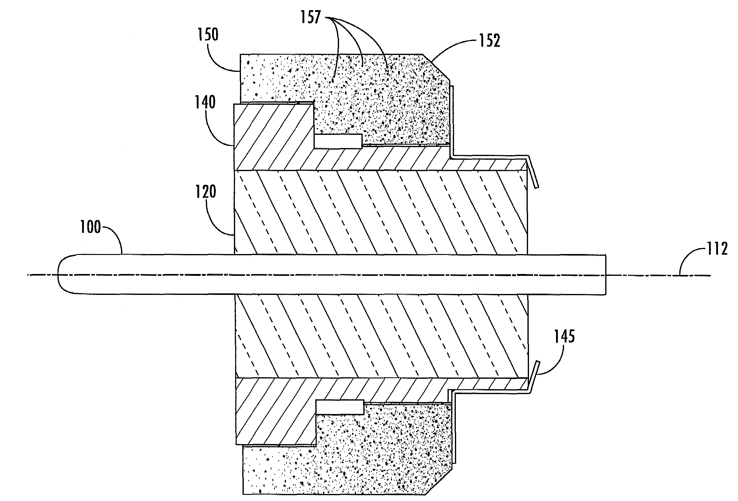
[0035]Attention is now directed to FIG. 4, wherein a first single-pin embodiment of a hermetically sealed coax type RF feed-through connector in accordance with the invention is diagrammatically illustrated in cross-section as comprising a generally longitudinal center signal pin 100, which may be made of gold-plated KOVAR (Reg. Tdmk), and having a longitudinal axis which is coaxial with the longitudinal axis 112 of the coaxial feed-through RF connector. As in the previous Figures, center pin 100, as well as the remaining components of the RF connector, are cylindrically symmetrical about the RF connector's axis 112. A first longitudinal portion 111 of the center pin 110 is surrounded by and hermetically sealed against a bore 131 of a generally cylindrical glass member 120, from which projects an interior distal end 113 of the pin 10. A second longitudinal portion 114 of the center pin 100 projects from an opposite end of bore 131 and terminates at an exterior distal end 115.

[0036]T...


PUM


Abstract

An RF feed-through connector has a single pin or multi-pins supported and hermetically sealed between a first portion of the connector facing the hermetically sealed interior portion of an electronics-containing housing and a second portion of the connector exposed to ambient conditions in which the electronics-containing housing is placed. The invention is particularly directed to a new hermetically sealed RF feed-through connector architecture in which the connector's outer shell contains a relatively low coefficient of thermal expansion (CTE) portion that enables it to be soldered to a low CTE insert that supports one or more hermetically sealed longitudinal signal pins. The connector's outer shell also includes a relatively high CTE portion that allows the shell to be readily joined as by welding to an adjacent support structure, such as a relatively high CTE aluminum housing and the like.

Description

FIELD OF THE INVENTION[0001]The present invention relates in general to single pin type feed-throughs, multi-pin headers, or multi-pin connectors in which one or more conductors or pins are supported and hermetically sealed between a first portion of the connector facing the hermetically sealed interior portion of an electronics-containing housing and a second portion of the connector exposed to ambient conditions in which the electronics-containing housing is placed. The invention is particularly directed to a new and improved hermetically sealed coax type RF feed-through architecture in which the connector's outer shell contains a relatively low coefficient of thermal expansion (CTE) portion that enables it to be soldered to a low CTE ferrule or insert that supports one or more hermetically sealed longitudinal signal pins. The connector's outer shell also includes a relatively high CTE portion that allows the shell to be readily joined as by welding to an adjacent support structur...

Claims


Application Information

Patent Timeline
Patent Type & Authority Patents(United States)
IPC IPC(8): H01R13/40
CPCH01B17/305H01R24/50H01R2103/00Y10S439/935
Inventor TAYLOR, EDWARD ALLEN
Owner WINCHESTER INTERCONNECT HERMETICS LLC
Why Eureka
Try Eureka