Thermal centrifugal vane type separator baffle

Inactive Publication Date: 2016-10-06
NETAFIL INC
View PDF2 Cites 10 Cited by
  • Summary
  • Abstract
  • Description
  • Claims
  • Application Information

AI Technical Summary

Benefits of technology

[0018]Another objective of the present invention to provide a lightweight and compact vane type as separator to provide improved collection of solid and liquid particulate while delivering an air/ga

Problems solved by technology

Rapid change in the flow direction results in the impact of the particles on the surfaces.
However, the currently ava

Method used


Image

  • Thermal centrifugal vane type separator baffle
  • Thermal centrifugal vane type separator baffle
  • Thermal centrifugal vane type separator baffle

Examples


Example

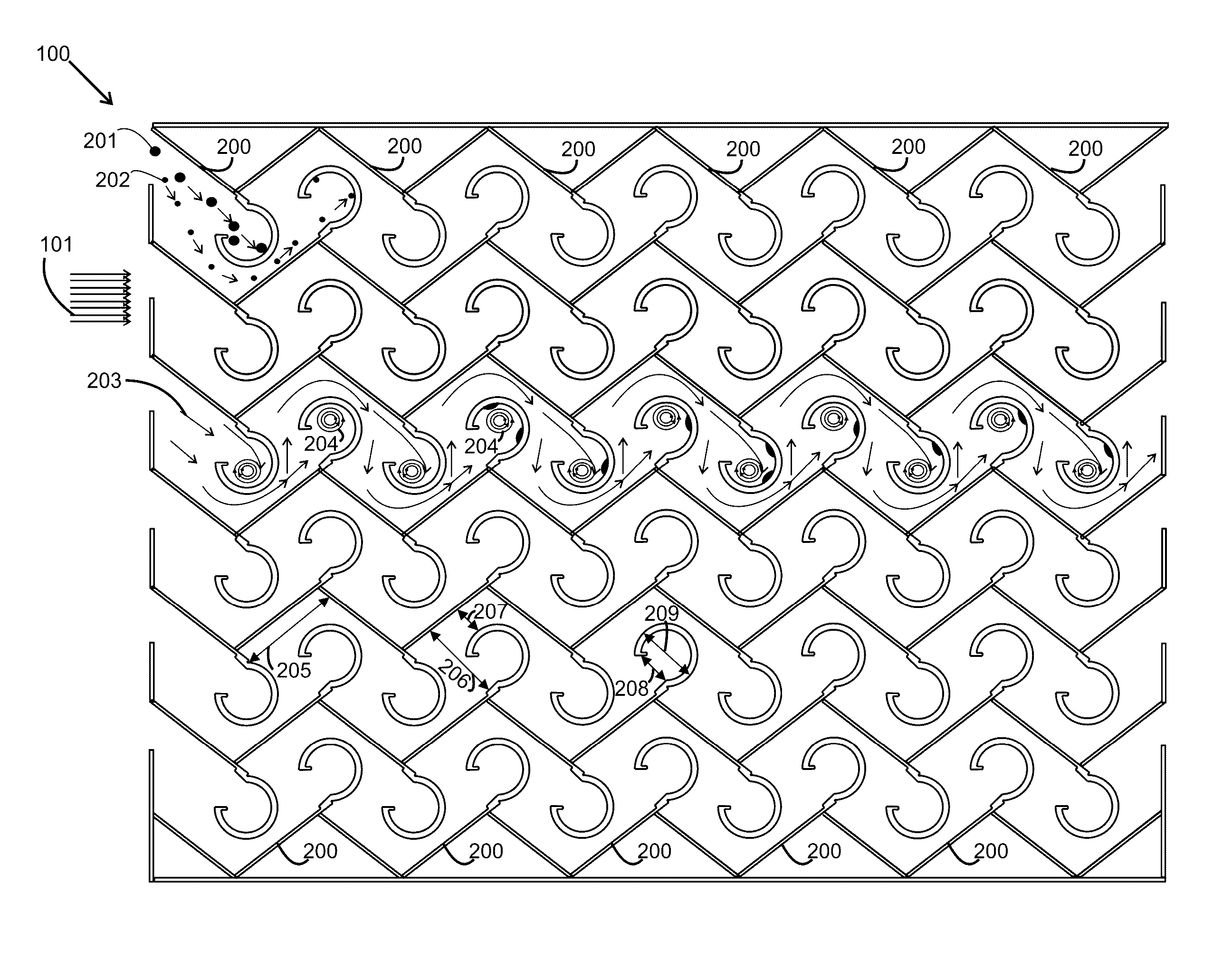
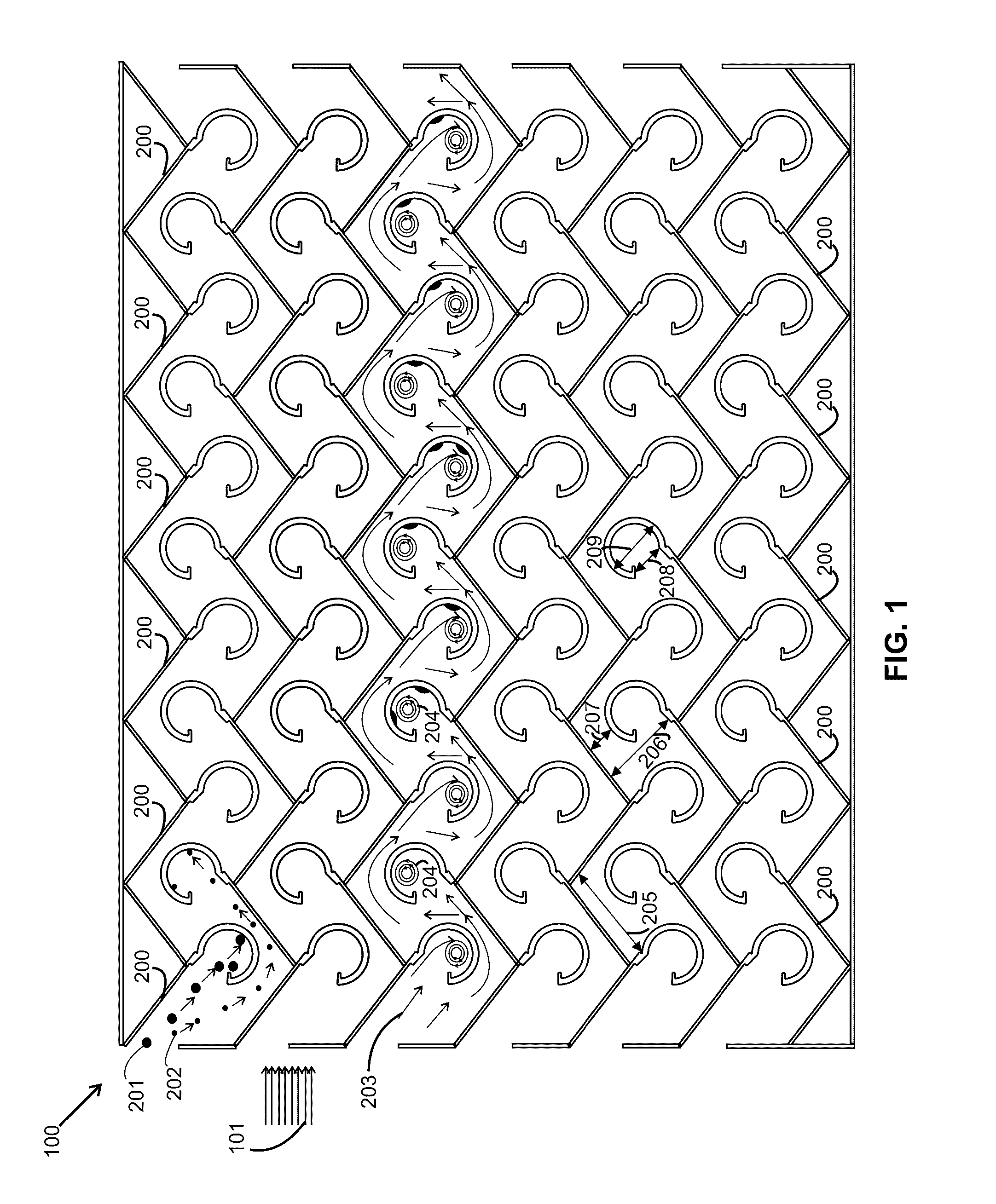
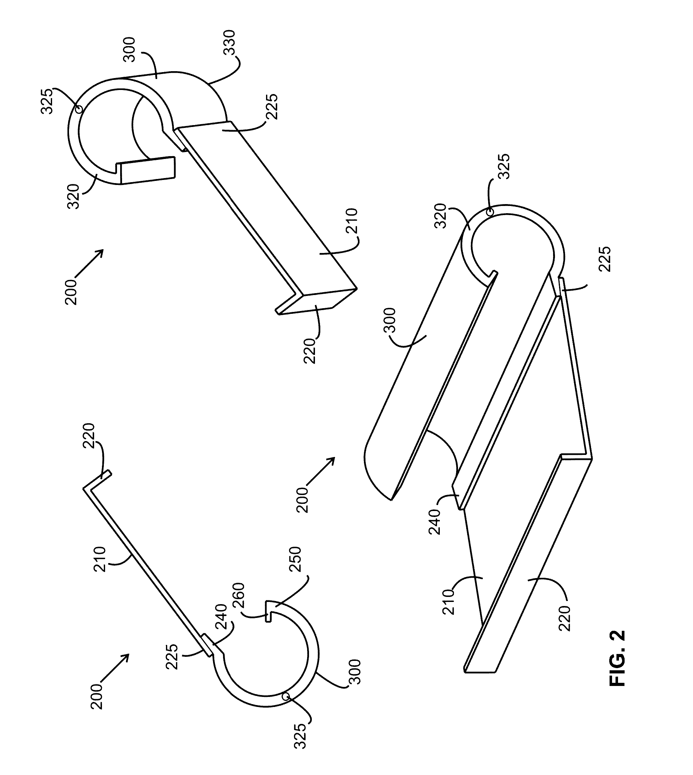
[0028]A preferred embodiment of the present particle separator is formed by attaching a series of especially designed vane-baffle elements 200 in a zig-zag configuration as shown in FIG. 1. One such vane-baffle element 200 is shown in FIG. 2. Each element 200 comprises of a planar vane sheet 210 (preferably made of sheet metal or any other shape retaining material). The vane sheet is bent on its first end 220 forming an L-shape cross section 220. This small bend is provided to weld two vanes 200 to each other forming the zig-zag vane configuration. The angle of the zig-zag vanes can be changed by the bent angle of the sheet. If the bent angle is 90 degrees, a 90 degree zig-zag partition is formed. The bend angle can be between 70 to 120 degrees, preferably 90 degrees for efficient particle separation.

[0029]A G-shaped annular tube 300 is attached to the second of each vane 200. The G-shaped annular tube 300 has an inner annular channel 310 for fluid flow as shown in FIG. 3, having an...


PUM

PropertyMeasurementUnit
Angleaaaaaaaaaa
Angleaaaaaaaaaa
Angleaaaaaaaaaa

Abstract

A gas purifier is disclosed for removing solid and liquid particles and to control humidity and volatile concentration in a gas stream. The device comprises of a plurality of vane-baffle elements. Each element comprising of a planar vane having a L-shaped cross section and a tubular baffle having a G-shaped cross section, wherein the baffle is attached to the vane forming a vane-baffle element. Each tubular baffle is annular allowing a secondary fluid to flow through it. A plurality of zig-zag shaped baffled partitioned are formed by attaching a plurality of vane-baffle elements to each other. A plurality of gas-stream passage ways are formed by vertically aligning said plurality of zig-zag partitions at a predefined partition spacing. A plurality of inlet manifolds are connected to the inlet ports to distribute a secondary fluid into each of said annular baffles, whereby the inlet temperature of said secondary fluid is controlled to control the temperature of the gas stream; and a plurality of outlet manifolds are connected to the outlet ports to collect the secondary fluid from each of the annular baffles.

Description

RELATED APPLICATION[0001]This application is related to and claims the benefits of priority to the U.S. provisional application No. 62 / 140,809, filed on Mar. 31, 2015, and titled “Thermal Centrifugal Vane Type Separator Baffle”, and related to a U.S. Design Pat. No. 373,625, filed on May 19, 1995 and issued on Sep. 10, 1996, which is incorporated by references herein.FIELD OF THE INVENTION[0002]The present invention relates generally to mist eliminators and wet scrubbers and particularly to baffle vane type separators.BACKGROUND OF THE INVENTION[0003]Many industries produce gaseous products, which have to be purified before exhausting to the ambient. Such gaseous produces may contain solid particles and liquid droplets of a variety of sizes, which have to be separated from the gas stream before emission to the surroundings. Therefore, a wide variety of particle and mist separators are developed to purify such gas streams.[0004]Many of the particle and mist separators are of a baffle...

Claims


Application Information

Patent Timeline
IPC IPC(8): B01D45/08
CPCB01D45/08
Inventor PEREIRA, MANUEL GOMES
Owner NETAFIL INC
Why Eureka
Try Eureka