
A shield machine mud cake removal device and removal method

A cleaning device and shield machine technology, applied to cleaning methods and tools, cleaning methods using liquids, cleaning methods using tools, etc., can solve the problem of affecting the tunneling speed of the shield machine, not having the conditions for stopping and cleaning, and the cleaning ability is not enough In place and other issues, to avoid the risk of manual cleaning, save economic resources, delay the effect of wear and tear

Active Publication Date: 2022-04-29
中电建路桥集团有限公司
View PDF5 Cites 0 Cited by
  • Summary
  • Abstract
  • Description
  • Claims
  • Application Information

AI Technical Summary

Problems solved by technology

Among them, during the tunneling process of the shield machine, the cutter head needs to continuously cut the soil so that the shield machine can move forward smoothly, but there are often some mud cakes due to the rising temperature during the cutting process or the failure of the muck modifier. Due to the good effect, part of the mud cake is formed into a mud cake and sticks to the cutter head, resulting in an increase in the torque of the cutter head and an increase in temperature, which eventually leads to serious wear of the cutter head, and the shield machine is forced to stop to replace the cutter. , which will seriously affect the tunneling speed of the shield machine and delay the construction period
[0003] The problem of mud cake cleaning on the cutter head has not been well solved. The traditional cleaning method not only has insufficient cleaning ability, but also needs to be shut down for cleaning. However, when the shield machine passes through some construction areas, it needs to pass through quickly and stably, and does not have the ability to stop Clean up conditions

Method used


Image

  • A shield machine mud cake removal device and removal method
  • A shield machine mud cake removal device and removal method
  • A shield machine mud cake removal device and removal method

Examples


Embodiment Construction

[0037] In order to make the technical problems, technical solutions and advantages to be solved by the present invention clearer, the following will describe in detail with reference to the drawings and specific embodiments, but the embodiments of the present invention are not limited thereto.

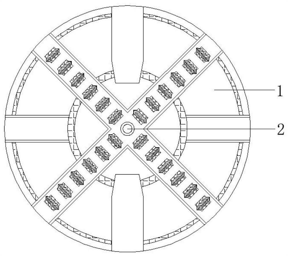
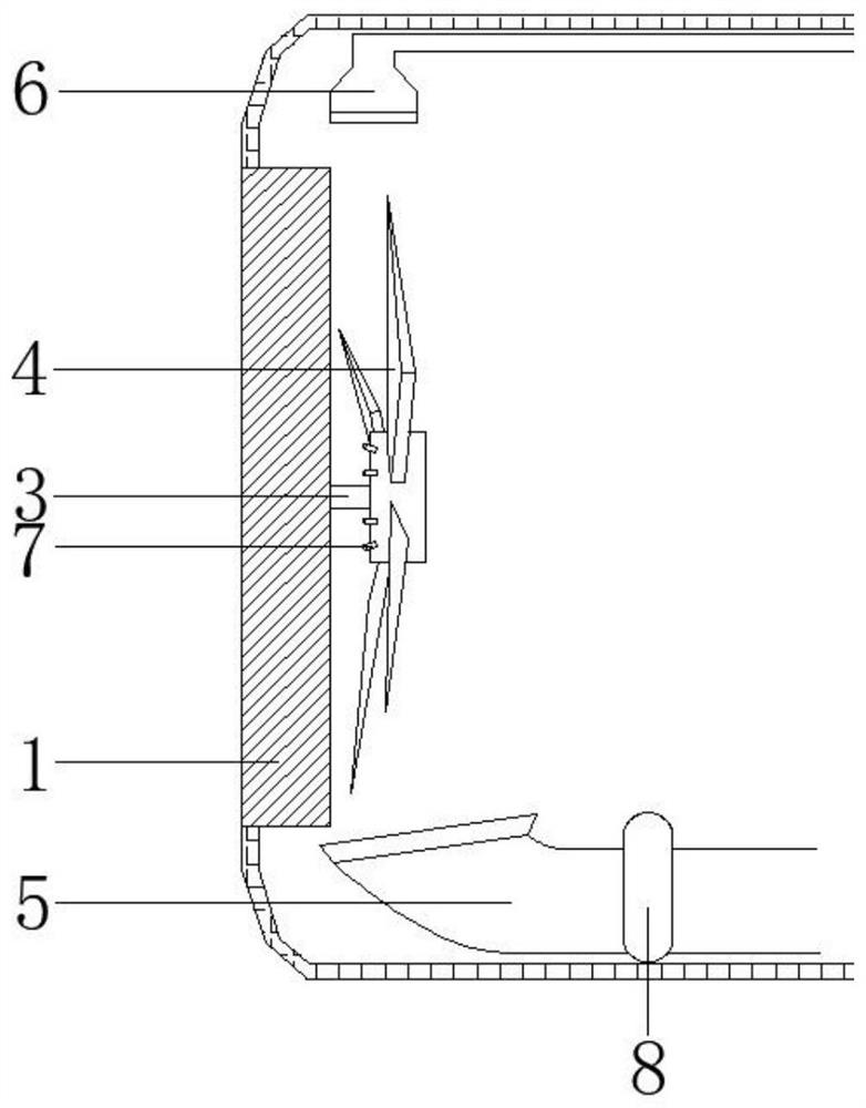
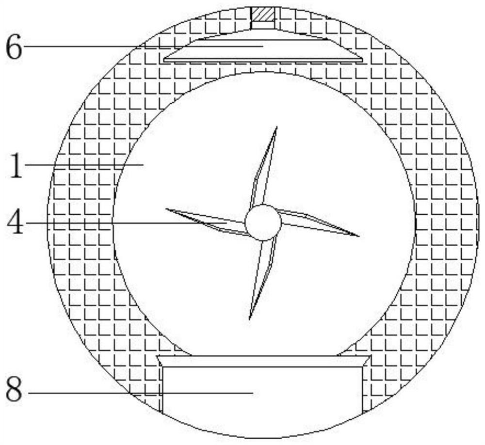
[0038] Such as Figure 1-Figure 2 As shown, the shield machine mud cake removal device of the present invention, the shield machine mud cake removal device includes a fan 6, a dredger 5 and a main cleaning turntable;

[0039] Wherein, the main cleaning turntable is connected with the cutter head panel of the shield machine, and is used to remove mud cake from the cutter head of the shield machine;

[0040] The fan 6 is arranged behind the cutterhead panel and above the main cleaning turntable for generating cold wind;

[0041] The mud suction machine 5 is arranged behind the cutterhead panel and below the main cleaning turntable for generating suction.

[0042] Preferably, the drill ...


PUM


Abstract

The invention relates to a mud cake removal device and method for a shield machine. The device includes a fan, a mud suction machine and a main cleaning turntable; the main cleaning turntable is connected to the cutter head panel of the shield machine for cleaning the shield machine knife The mud cake on the disk; the fan is set behind the cutter head panel and above the main cleaning turntable to generate cold air; the mud suction machine is set behind the cutter head panel and below the main cleaning turntable to generate suction. The technical scheme of the present invention adopts the form of a cleaning turntable to clean the mud cake, and realizes the reverse cleaning method opposite to the rotation direction of the cutter head through the reverse rotation shaft, which saves resources; the cleaning speed can be accelerated by using the fan-assisted cleaning, and more effective The temperature of the cutter head panel can be lowered to effectively delay the wear of the cutter; the dredge suction machine can not only effectively speed up the cleaning speed of the mud cake, but also accelerate the collection of fallen soil and transport it to the soil warehouse, while ensuring the protection of the cutter head panel of the shield machine. The cleanliness of the empty compartment behind.

Description

technical field [0001] The invention relates to the field of shield machine auxiliary equipment manufacturing, in particular to a shield machine mud cake removal device and a removal method. Background technique [0002] At present, shield machines are widely used in digging underground tunnels, and are famous for their economy and safety. Among them, during the excavation process of the shield machine, the cutter head needs to continuously cut the soil so that the shield machine can move forward smoothly, but there are often some mud cakes due to the rising temperature during the cutting process or the failure of the muck modifier. Due to the good effect, part of the mud cake formed into a mud cake and stuck on the cutter head, resulting in an increase in the torque of the cutter head and an increase in temperature, which eventually led to severe wear of the cutter head, and the shield machine was forced to stop to replace the cutter. , which will seriously affect the tunn...

Claims


Application Information

Patent Timeline
Patent Type & Authority Patents(China)
IPC IPC(8): B08B3/02B08B1/04B08B1/00B08B5/02B08B13/00E21D9/08
CPCB08B3/022B08B5/02B08B13/00E21D9/08B08B1/165B08B1/32
Inventor 张福荣郑健林君君徐兴芃柯兰玲游通绿詹明尧黄挺
Owner 中电建路桥集团有限公司
Learn More