Milling Tool and Cutting Element for Use in a Milling Tool

a technology of cutting element and milling tool, which is applied in the field of milling tools, can solve the problems of dirt particles being lodged in the operation at the bottom of the receptacle and the bottom side of the cutting element, and achieve the effects of preventing bending (sagging) of the cutting element in the area of the fastening element, less prone to wear, and strong material

Active Publication Date: 2016-10-06
LEDERMANN
View PDF16 Cites 6 Cited by
  • Summary
  • Abstract
  • Description
  • Claims
  • Application Information

AI Technical Summary

Benefits of technology

[0017]In an advantageous embodiment of the invention, it is provided that the fastening element is a countersunk head screw and that the wedge-shaped pressure surface of the cutting element has a depression that is matched to the shape of the head of the countersunk head screw and opens at the lateral face of the cutting element and has the shape of a cone section. In this way, the wedge-shaped pressure surface and the associated fastening element are realized in a simple way.
[0018]In an advantageous further embodiment of the invention, it is provided that a point of the three-point support is arranged in the area of the fastening element. In this way, the cutting element is contacting directly the bottom of the receptacle in the area of the fastening element in which the greatest contact pressure of the cutting element relative to the bottom of the receptacle is existing. In this way, it is prevented that the cutting element will bend in the area of the fastening element under the pressure of the fastening element.
[0019]In an advantageous further embodiment of the cutting element according to the invention, it is provided that the cutting element has a cutout with an opening at the lateral face of the cutting element for receiving the fastening element and that the cutout adjoins a support pad of the cutting element. Since the cutout for receiving the fastening element is open at the lateral face of the cutting element, it is possible in a simple way to exert by means of the fastening element pressure on the cutting element in a defined direction. Accordingly, the cutting element can be pressed in a simple way by means of the fastening element into the wedge-shaped space of the receptacle of the support member of the milling tool according to the invention. Since the cutout immediately adjoins a support pad of the cutting element and since the cutout serves for receiving the fastening element, the cutting element in the area of the fastening element, where the greatest contact pressure is exerted on the cutting element by the fastening element, is directly contacting the bottom of the receptacle of the support member of the milling tool according to the invention. Accordingly, bending (sagging) of the cutting element in the area of the fastening element is prevented.
[0020]In an advantageous further embodiment of the cutting element according to the invention, it is provided that in the cutting element a recessed cuttings guide for guiding away cuttings (chips) is formed and provided with an opening that in the mounted state of the cutting element opens at the exterior surface of the support member. The recessed cuttings guide provides a space for guiding away cuttings (chips) and this space is exclusively arranged within the cutting element. Accordingly, when machining a workpiece, the resulting cuttings (chips) are exclusively guided through the cutting element. In this way, wear of the support member of the milling tool as a result of the action of guiding away cuttings (chips) is avoided. The support member therefore can be produced of lighter and softer material. Wear on the cutting element by the guiding action for the cuttings (chips) is more beneficial than wear on the support member by such a guiding action for the cuttings (chips) because the cutting element can be exchanged. Moreover, the cutting element can be produced of stronger material that is less prone to wear. Since the recessed cuttings guide for moving away cuttings (chips) is provided exclusively within the cutting element, the intermediate spaces between the cutting element and the support member become less soiled. The cuttings of the workpiece being machined are directly guided away from the milling tool by means of the cutting element and, ideally, to not even contact the support member of the milling tool at all.

Problems solved by technology

Another difficulty is that dirt particles become lodged in operation at the bottom of the receptacles and at the bottom side of the cutting elements.

Method used


Image

  • Milling Tool and Cutting Element for Use in a Milling Tool
  • Milling Tool and Cutting Element for Use in a Milling Tool
  • Milling Tool and Cutting Element for Use in a Milling Tool

Examples


Embodiment Construction

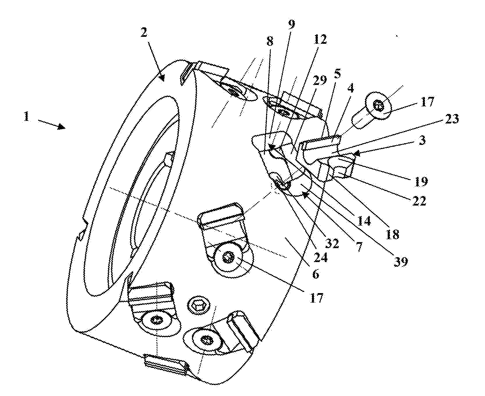
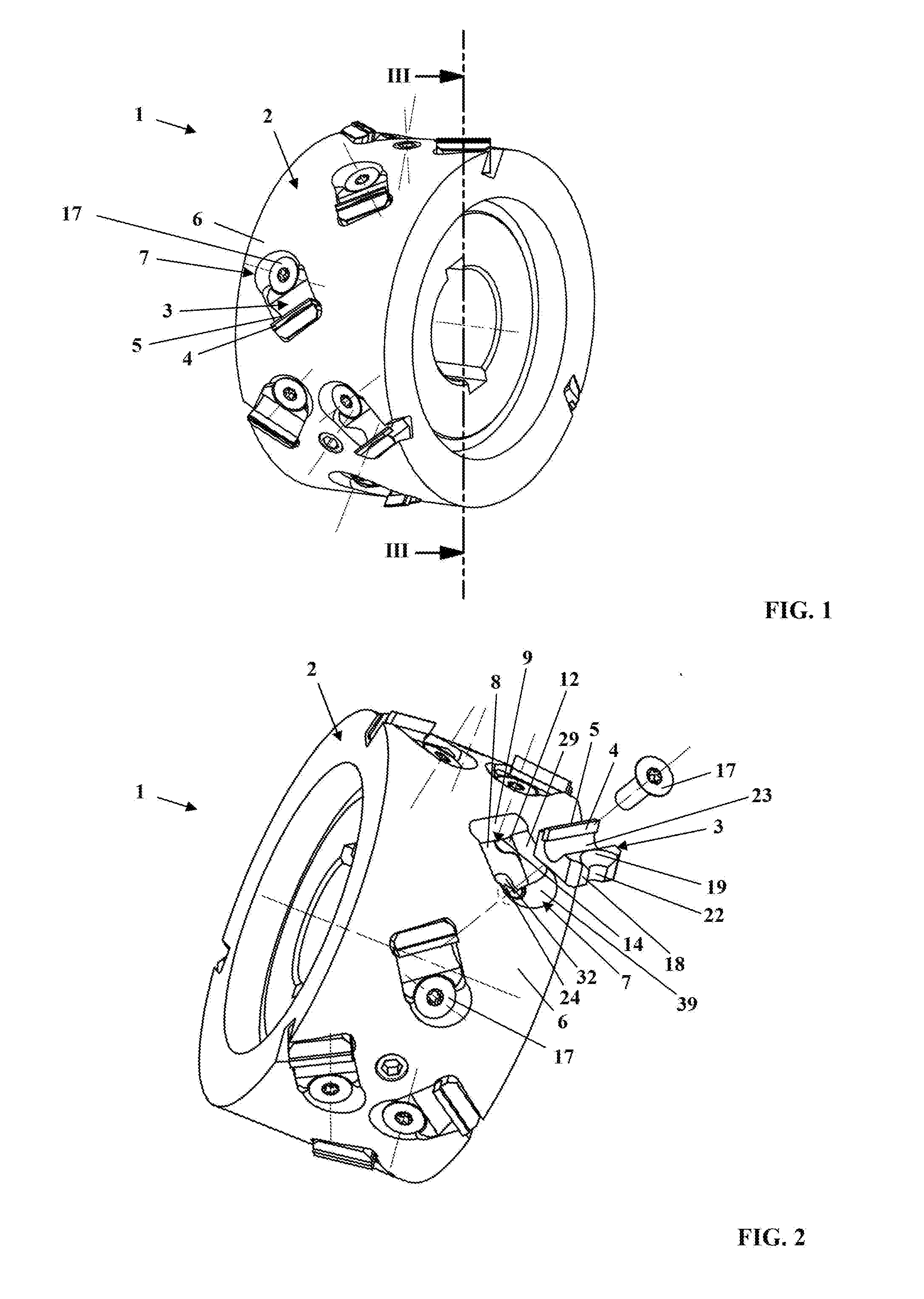
[0027]FIG. 1 shows in a perspective illustration a milling tool 1 comprising a support member 2 and several cutting elements 3. The support member 2 comprises a substantially cylindrical outer contour. Receptacles 7 are arranged in the circumferential exterior surface of the support member 2. The receptacles 7 are realized by recesses formed in the exterior surface 6 of the support member 2. The exterior surface 6 corresponds to the circumferential wall surface of the support member 2. Cutting elements 3 are inserted in the receptacles 7 of the support member 2. The cutting elements 3 comprise a cutter 4 with a cutting edge 5. The cutter 4 is connected fixedly so as to be immobile to a base body of the cutting element 3. The cutting elements 3 are secured by means of countersunk head screws 17 in the receptacles 7 of the support member 2. As a result of the cylindrical outer contour of the support member 2, the cutting edges 5 of the cutters 4 are arranged on a straight (linear) env...


PUM


Abstract

A milling tool has a support member with an exterior surface with at least one receptacle, wherein the at least one receptacle has a bottom. At least one cutting element provided with a cutter having a cutting edge is positioned in the at least one receptacle. A three-point support is arranged between the at least one cutting element and the bottom of the at least one receptacle for positioning the cutting edge relative to the bottom of the at least one receptacle. The three-point support comprises three support pads arranged at a bottom side of the at least one cutting element and/or three projections arranged at the bottom of the at least one receptacle.

Description

BACKGROUND OF THE INVENTION[0001]The invention relates to a milling tool comprising a support member and at least one cutting element, wherein the cutting element comprises a cutter with a cutting edge, wherein the support member has a receptacle at its exterior surface for receiving the cutting element and wherein the receptacle has a bottom. The invention further relates to a cutting element for use in such a milling tool.[0002]DE 20 2014 104 712 U1 discloses a milling tool with a substantially cylindrical outer contour provided at its circumferential exterior surface with a plurality of receptacles for receiving cutting elements. The cutting elements mounted in the receptacles are resting flat against the bottom of the receptacles and are secured by means of a screw in the receptacles.[0003]US 2011 / 0305533 A1 discloses a comparable milling tool in which a portion of the receptacle is utilized as a recess for guiding away cuttings.[0004]For producing a uniform surface of a workpie...

Claims


Application Information

Patent Timeline
Patent Type & Authority Applications(United States)
IPC IPC(8): B23C5/04B23C5/20B23C5/22
CPCB23C5/04B23C5/2239B23C5/207B23C2210/168B23C2200/086B23C2200/361B23C2210/165B23C2200/0416B23C5/08B23C5/2234B23C2210/04B27G13/04B23C2200/161B23C2200/128B23C5/2213B23C5/202
Inventor WESTFAL, EWALDSITZLER, BENJAMINHAMPEL, STEFFEN
Owner LEDERMANN
Why Eureka
Try Eureka