Method of manufacturing heat dissipation device

Active Publication Date: 2016-10-06
ASIA VITAL COMPONENTS SHENZHEN CO LTD
View PDF10 Cites 0 Cited by
  • Summary
  • Abstract
  • Description
  • Claims
  • Application Information

AI Technical Summary

Benefits of technology

The present invention provides a method for manufacturing a heat dissipation device with fewer steps and at reduced manufacturing cost. The method includes the steps of providing a heat transfer unit with a wick structure and a working fluid, connecting a frame to the heat transfer unit, and spot welding the heat transfer unit to the frame. This method eliminates the need for adhesive agents or tape, reducing material and production costs, and avoids the problem of assembling tolerance. Additionally, the method improves compatibility between the heat dissipation device and the heat transfer unit.

Problems solved by technology

These thin, light and high-performance hand-held mobile devices have limited internal space while their internal electronic elements, such as the Central Processing Unit (CPU), the integrated circuits and the like, produce a large amount of heat during operation at a high speed.
However, an additional cost for applying the adhesive agent or the adhesive tape is required.
In the process of soldering, the heat transfer element and the frame are subjected to high temperature and tend to shift relative to each other in their positions, and the solder located between the heat transfer element and the frame also results in increased accumulated tolerance between the heat transfer element, the frame and the heat generating element, causing difficulty in the subsequent assembling process.
Therefore, the manufacturing cost of the thin heat dissipation device is increased, and only a heat pipe can be used as a heat transfer member thereof.
This type of heat dissipation device is inconvenient and impractical for use because it could not be used with a non-C-shaped heat transfer member or a non-deformable heat transfer member.

Method used


Image

  • Method of manufacturing heat dissipation device
  • Method of manufacturing heat dissipation device
  • Method of manufacturing heat dissipation device

Examples


Embodiment Construction

[0025]The present invention will now be described with some preferred embodiments thereof and by referring to the accompanying drawings. For the purpose of easy to understand, elements that are the same in the preferred embodiments are denoted by the same reference numerals.

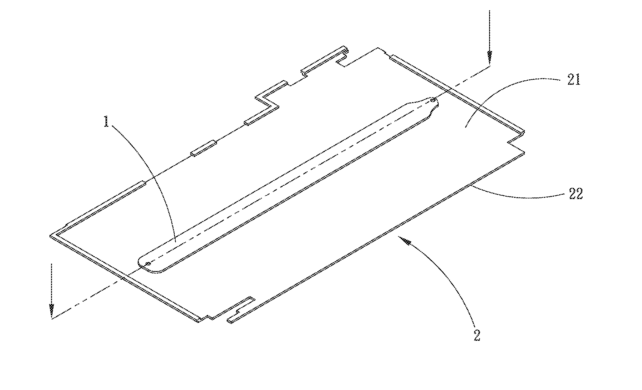
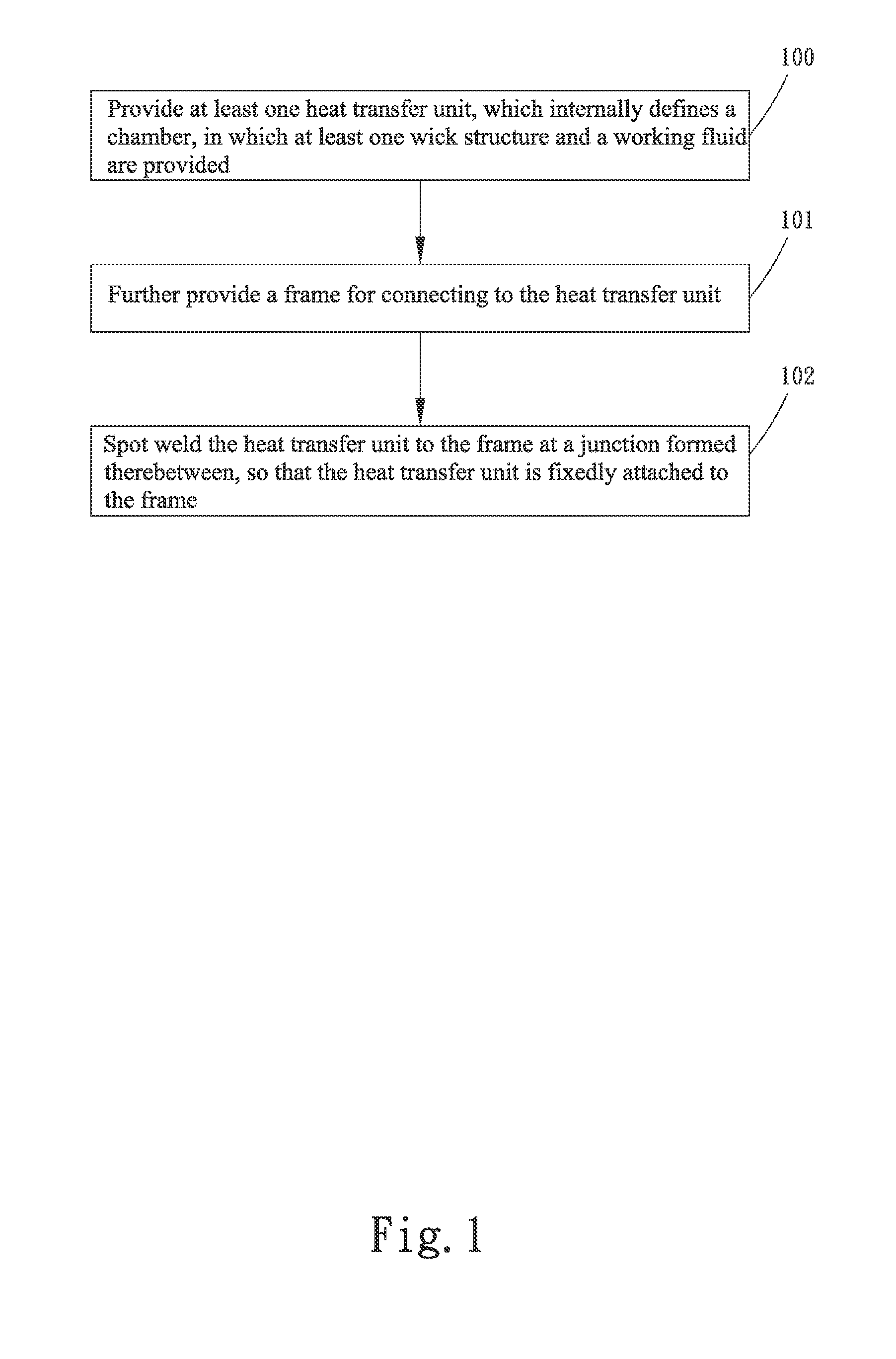
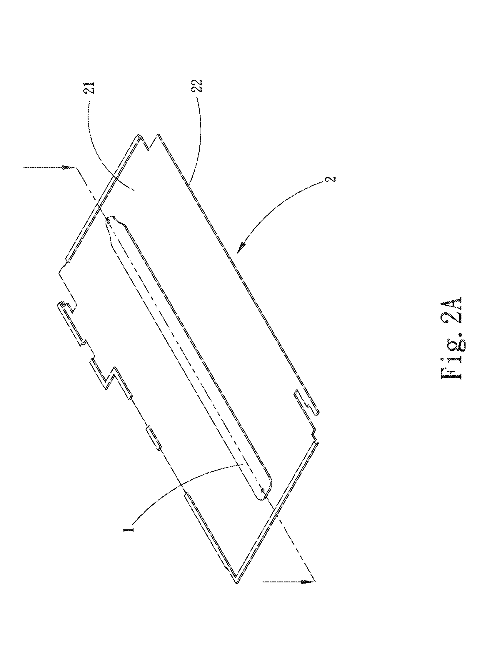
[0026]Please refer to FIGS. 1, 2A and 2B, wherein FIG. 1 is a flowchart showing the steps 100, 101, and 102 included in a first embodiment of a method of manufacturing heat dissipation device according to the present invention, and FIGS. 2A and 2B are assembled perspective and sectional views, respectively, showing the first embodiment of the manufacturing method according to the present invention. For the purpose of conciseness, the present invention is also briefly referred to as the manufacturing method herein.

[0027]In the step 100, at least one heat transfer unit is provided. The heat transfer unit 1 internally defines a chamber, in which at least one wick structure and a working fluid are provided.

[0028]More...


PUM


Abstract

A method of manufacturing heat dissipation device includes the steps of providing at least one heat transfer unit; further providing at least one frame for connecting to the at least one heat transfer unit; and spot welding the heat transfer unit to the frame at a junction formed therebetween, so that the heat transfer unit is fixedly attached to the frame. With the above method, the steps for assembling the heat transfer unit to the frame are effectively reduced, and the material and production costs for applying adhesive agent or adhesive tape are also saved.

Description

FIELD OF THE INVENTION[0001]The present invention relates to a heat dissipation device, and more specifically, to a method of manufacturing heat dissipation device that enables a heat dissipation device to be manufactured with fewer steps and at largely reduced manufacturing cost.BACKGROUND OF THE INVENTION[0002]As the advancement of the mobile technology, users' demand for thin, light and high-performance hand-held mobile devices, such as cell phones, tablet PCs, Personal Digital Assistants (PDAs) and so on, has also largely increased. These thin, light and high-performance hand-held mobile devices have limited internal space while their internal electronic elements, such as the Central Processing Unit (CPU), the integrated circuits and the like, produce a large amount of heat during operation at a high speed. For the hand-held mobile devices to maintain normal operation and have prolonged service life, it is foremost to effectively dissipate the heat produced by the internal elect...

Claims


Application Information

Patent Timeline
IPC IPC(8): B23P15/26
CPCB23P15/26
Inventor YANG, HSIU-WEI
Owner ASIA VITAL COMPONENTS SHENZHEN CO LTD
Why Eureka
Try Eureka