Traveling wind intake structure for saddled vehicle

a technology of intake structure and traveling wind, which is applied in the direction of weather guards, transportation and packaging, bicycle equipment, etc., can solve the problems of inability to efficiently guide the traveling wind toward, easy to be complicated in the internal structure of the vehicle body cover, etc., and achieve the reduction of the weight of the guide member, the reduction of interference noise, and the increase of the introduction portion.

Active Publication Date: 2016-10-06
HONDA MOTOR CO LTD
View PDF17 Cites 4 Cited by
  • Summary
  • Abstract
  • Description
  • Claims
  • Application Information

AI Technical Summary

Benefits of technology

[0022]According to the seventh aspect of the present invention, when the louver member swings frontward, the position restraining unit restrains the relative positions such that the front end of the guide member is spaced from the upper surface of the meter visor. Thereby, contact of the guide member and the meter visor can be avoided, and thus, an interference noise can be prevented from being generated.
[0023]According to the eighth aspect of the present invention, the traveling wind intake structure further includes the position adjusting unit configured to allow the wind screen to move up and down and configured to adjust the relative positions of the lower end of the wind screen and the vehicle body. Thereby, the traveling wind introduced through the introduction portion can be increased and reduced.
[0024]According to the ninth aspect of the present invention, when the wind screen is moved upward, the lower end of the wind screen is located downward of the lower end of the guide member in the side view. Thereby, even if a foreign matter enters through the introduction portion, reaching of the foreign matter to the guide member can be suppressed. Moreover, the guide member can be reduced in weight, and thus, ease of operation of the louver member to swing frontward and rearward can be improved.
[0025]According to the tenth aspect of the present invention, the protrusion convexly protruding downward is formed in the lower end portion of the wind screen, and the recess which is convexly recessed upward is formed in the lower end portion of the guide member. Thereby, a long distance between the lower end portion of the wind screen and the lower end portion of the guide member can be ensured, and thus, the traveling wind introduced through the introduction portion can be guided long along the upper surface of the meter visor, and the louver member can effectively change the travel direction of the traveling wind (or the deflecting effect can be improved).
[0026]According to the eleventh aspect of the present invention, the opening for introducing the traveling wind rearward of the protrusion is formed in the protrusion, and when the wind screen is moved upward, the upper end of the opening is located downward of the lower end of the guide member in the side view. Thereby, even if a foreign matter enters through the opening, direct reaching of the foreign matter to the guide member can be suppressed. Moreover, the guide member can be reduced in weight, and thus, ease of operation of the louver member to swing frontward and rearward can be improved. Further, a constant traveling wind can be introduced through the opening, and a comfortable traveling wind can be guided toward the vehicle occupant.

Problems solved by technology

Specifically, in the case of a vehicle large in size, it is difficult to guide a traveling wind to a position lower than an upper surface of the meter visor, and accordingly the structure cannot efficiently guide the traveling wind toward a vehicle occupant adaptively to an occupant's riding position.
Moreover, the structure in which the inner wind passage is formed within the vehicle body cover has a problem in that the vehicle body cover is prone to be complicated in its internal structure.

Method used


Image

  • Traveling wind intake structure for saddled vehicle
  • Traveling wind intake structure for saddled vehicle
  • Traveling wind intake structure for saddled vehicle

Examples


Embodiment Construction

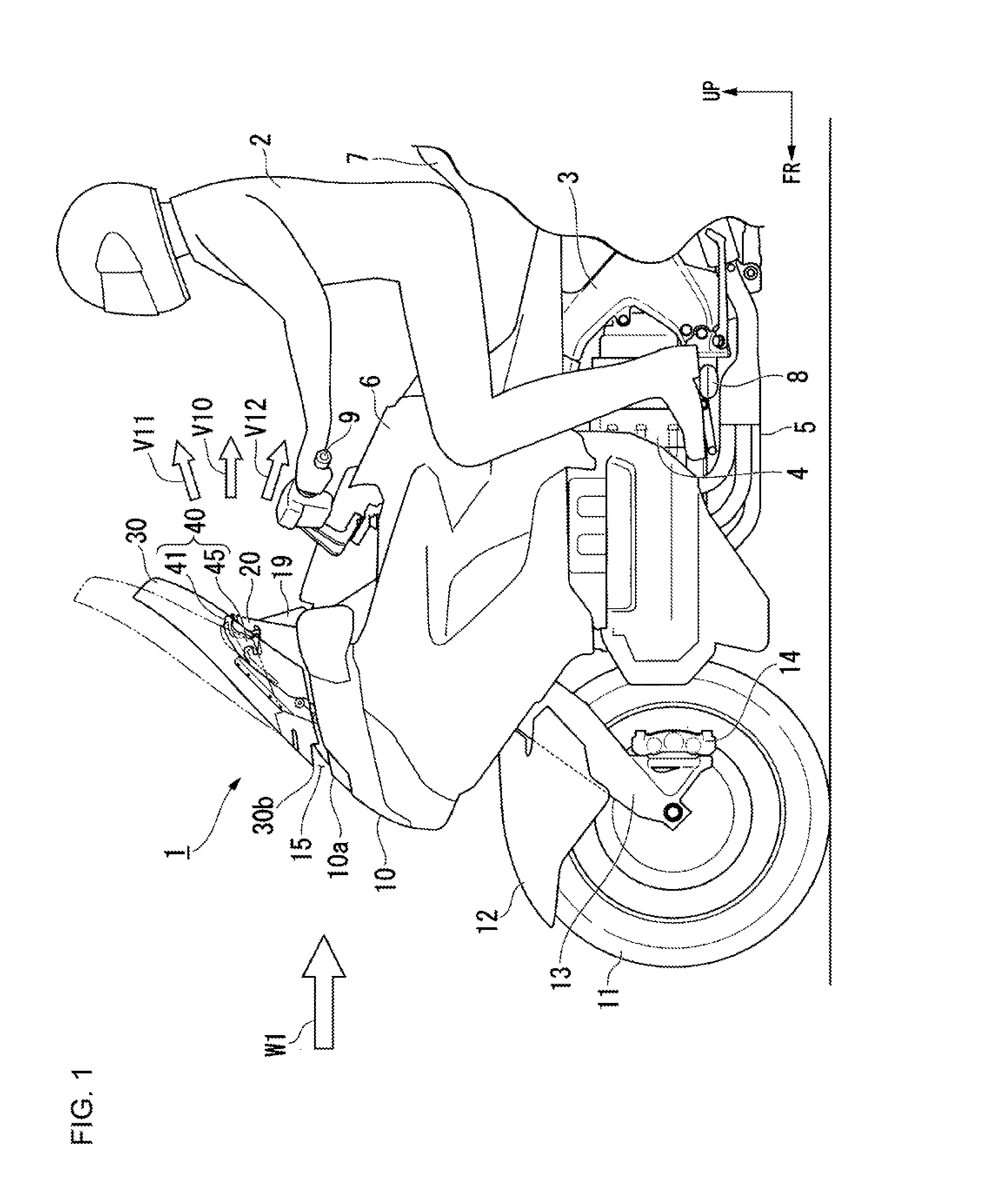
[0036]Embodiments of the present invention will be described below with reference to the drawings. Note that frontward, rearward, leftward, rightward and other directions in the following description are the same as those of a vehicle described below, unless otherwise specified. Moreover, an arrow FR indicating a vehicle frontward direction, an arrow LH indicating a vehicle leftward direction, and an arrow UP indicating a vehicle upward direction are given in appropriate portions in the drawings as used in the following description.

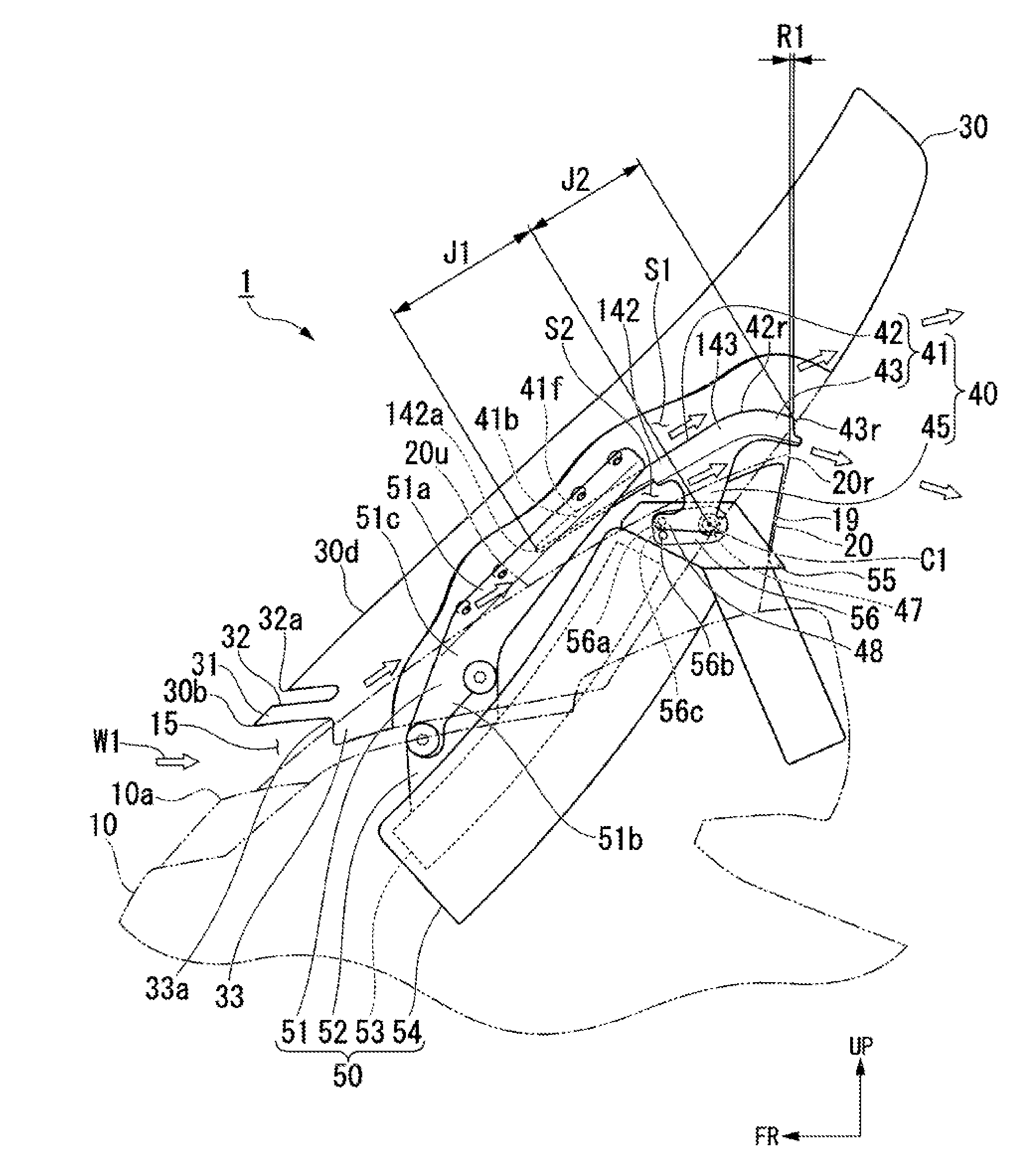
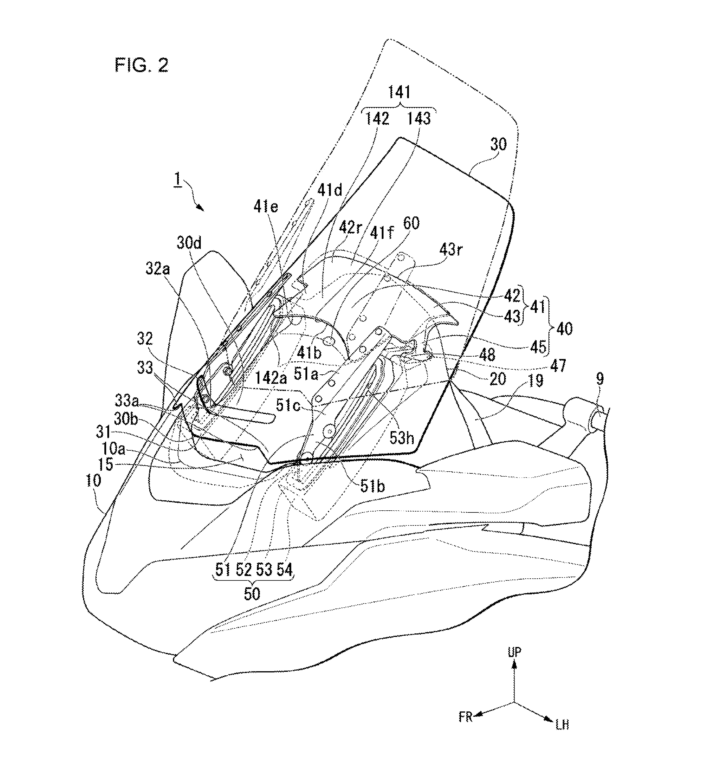
[0037]FIG. 1 illustrates a front portion of a vehicle body of a motorcycle as an example of a saddled vehicle. Referring to FIG. 1, the motorcycle has a traveling wind guide device 1 provided in a vehicle front portion and configured to guide a traveling wind W1 toward a vehicle occupant 2. The traveling wind guide device 1 is supported in a front portion of a vehicle body frame 3.

[0038]An engine 4 of a horizontally facing type, for example, is mounted be...


PUM


Abstract

A traveling wind intake structure for a saddled vehicle, comprising a meter visor covering a meter from above; and a wind screen covering the meter visor from above, wherein an introduction portion for introducing a traveling wind rearward of the wind screen is formed between a lower end of the wind screen and a vehicle body, a gate-type louver member is provided between the wind screen and the meter visor, and is formed by a plate-shaped guide member for guiding rearward the traveling wind introduced through the introduction portion, and leg members extending downward from left and right end portions of the guide member in a vehicle width direction, and the leg members are each provided with a shaft portion extending along the vehicle width direction and supporting the louver member in a frontward and rearward swingable manner.

Description

[0001]The present application relates to a traveling wind intake structure for a saddled vehicle.BACKGROUND OF THE INVENTION[0002]Heretofore, a traveling wind intake structure for a saddled vehicle has been disclosed for example in Japanese Patent Application Publication No. 2001-10573 (JP '573) and Japanese Patent Application Publication No. 2014-113988 (JP '988). JP '573 discloses a structure in which a wind screen covering a meter visor from above is provided in a vehicle front portion, an inlet port for a traveling wind is formed in a lower portion of the wind screen, and a baffle plate portion for guiding upwardly rearward the traveling wind introduced through the inlet port is formed in front of the meter visor. JP '988 discloses that a wind introduction portion is formed in a front portion of a vehicle body cover, and an inner wind passage through which part of a traveling wind taken into an inside of the vehicle body cover through the wind introduction portion is guided to a...

Claims


Application Information

Patent Timeline
Patent Type & Authority Applications(United States)
IPC IPC(8): B62J17/04
CPCB62J17/04B62J17/10
Inventor HAGIMOTO, MASASHIWAKITA, NOBUTAKAKUSUDA, ATSUSHIKAITA, KIHOKO
Owner HONDA MOTOR CO LTD
Why Eureka
Try Eureka