A method for controlling a boat comprising a pivotable drive unit, and a electronic vessel control unit for steering a boat

a technology of electronic vessel control and steering device, which is applied in the direction of motor-driven steering, steering initiation, instruments, etc., can solve the problems of cumbersome design procedure and/or manufacturing procedure, and achieve the effect of increasing the possibility of controlling the behavior of the boa

Active Publication Date: 2016-10-06
VOLVO PENTA AB
View PDF0 Cites 11 Cited by
  • Summary
  • Abstract
  • Description
  • Claims
  • Application Information

AI Technical Summary

Benefits of technology

[0016]Thus, with a control method according to the above, the boat roll angle may be controlled by virtue of the fact that the each drive unit is pivotable around two axes of rotation, viz the drive unit longitudinal axis and the steering axis. This implies that the control method may be used for any boat that has one or more drive units that are adapted to be pivoted around the above two axes of rotation. This in turn implies a reduced need for modifying the hardware of the boat, such as the shape of the hull or the type of propulsion system, in order to obtain appropriate roll characteristics doting operation.
[0026]The fact that the target roll angle is based on the target direction of travel as well as the speed of the boat implies that there is an appropriately low risk that the boat will capsize, even if the boat makes a sharp turn at a high speed.
[0032]The above alternative of the control method according to the present disclosure implies that the trim of the boat may be controlled even if one or more of the two drive units is mounted to the stem of the boat. This in turn implies increased possibilities to control the behavior of the boat.

Problems solved by technology

This in turn may result in a cumbersome design procedure and / or manufacturing procedure.

Method used


Image

  • A method for controlling a boat comprising a pivotable drive unit, and a electronic vessel control unit for steering a boat
  • A method for controlling a boat comprising a pivotable drive unit, and a electronic vessel control unit for steering a boat
  • A method for controlling a boat comprising a pivotable drive unit, and a electronic vessel control unit for steering a boat

Examples


Embodiment Construction

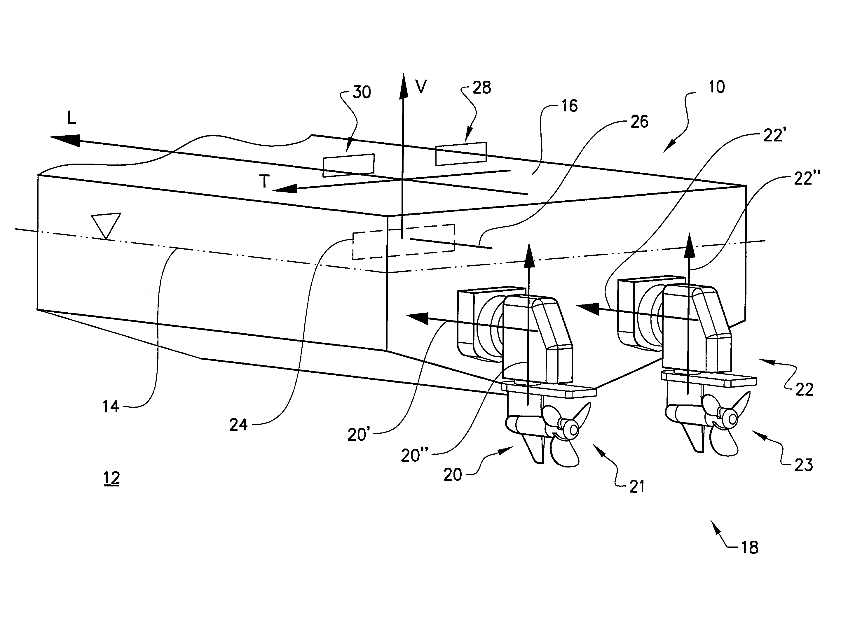
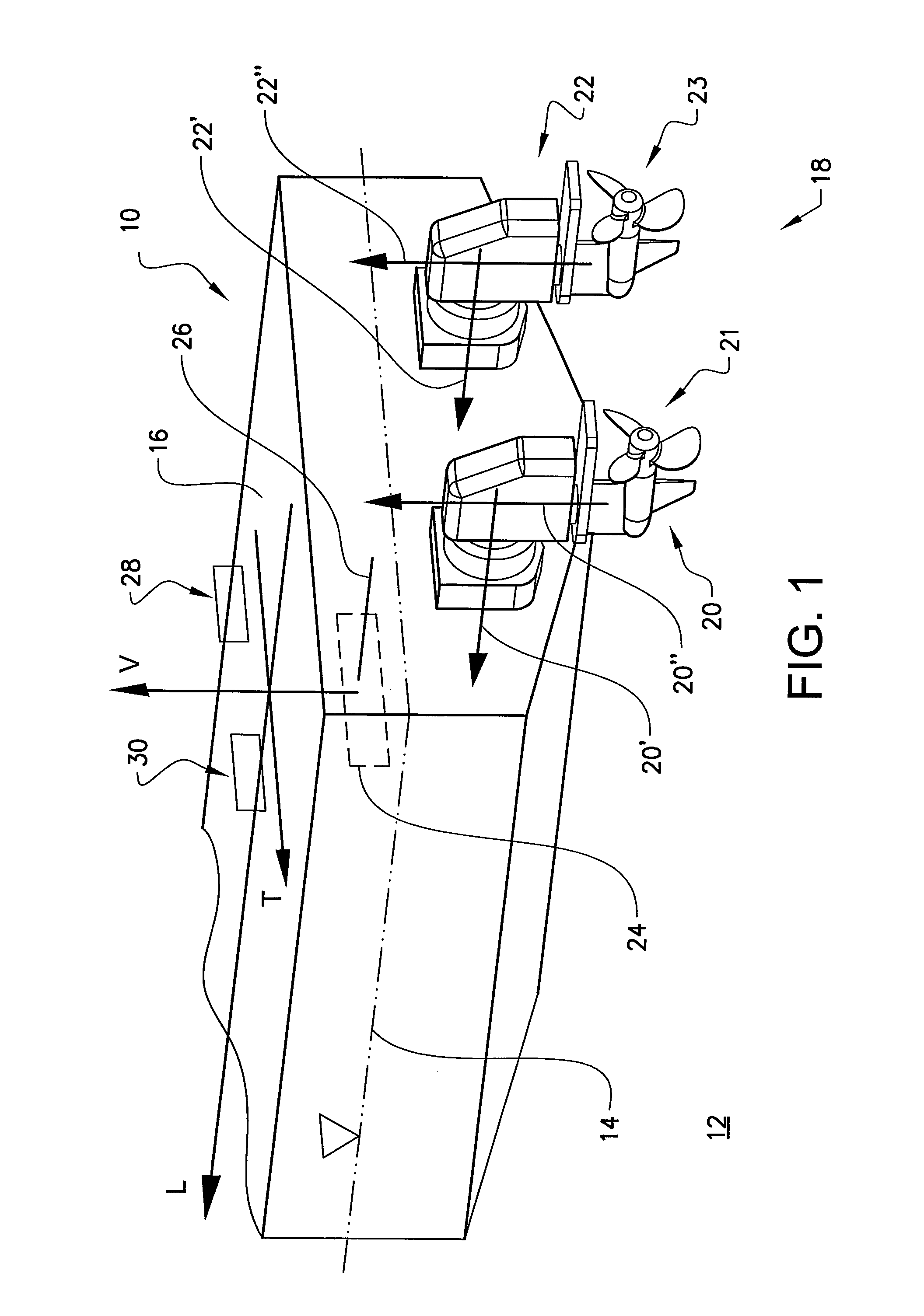
[0061]The invention will below be described in relation to a boat 10 such as the pleasure boat illustrated in FIG. 1. However, it should be noted that the expression “boat” encompasses any type of aquatic vessel, such as a yacht or ship.

[0062]The boat 10 is adapted to float in a body of water 12. The body of water has as still water level 14. The boat comprises a hull 16 having a longitudinal extension along a hull longitudinal axis L, a lateral extension along a hull lateral axis T and a vertical extension along a hull vertical axis V.

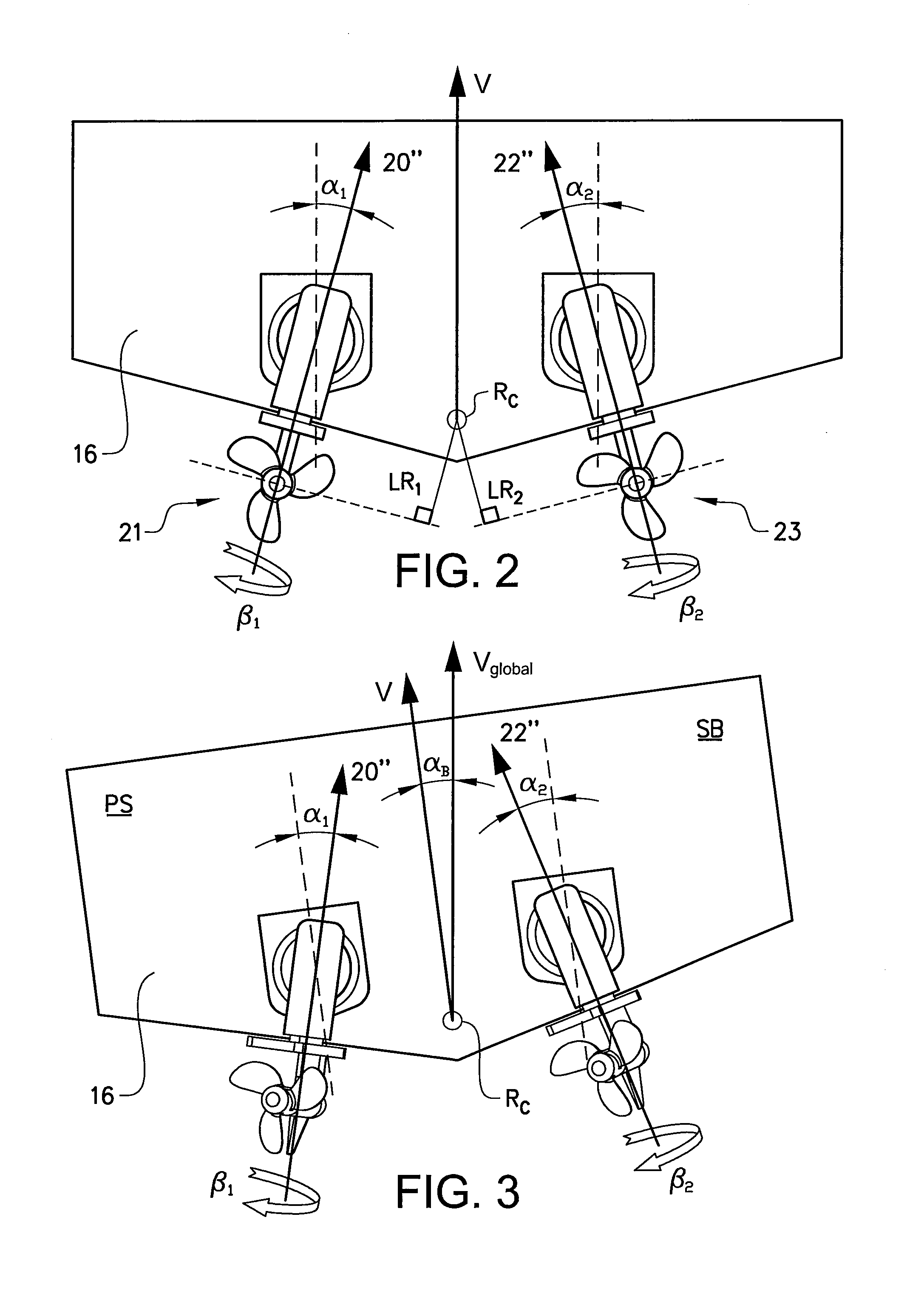
[0063]Moreover, the boat 10 comprises a set 18 of drive units. The set of drive units comprises at least one drive unit. In the implementation of the boat 10 illustrated in FIG. 1, the drive unit set 18 comprises two drive units, viz a first drive unit 20 and a second drive unit 22.

[0064]Each drive unit 20, 22 in the set 18 is arranged such that it, during driving of the boat 18, is adapted to be at least partially submerged into the body of water 12....


PUM


Abstract

A method is provided for controlling a boat. The boat is adapted to float in a body of water. The boat includes a hull having a longitudinal extension along a hull longitudinal axis, a lateral extension along a hull lateral axis and a vertical extension along a hull vertical axis. The boat also includes a set of drive units, the set of drive units comprising at least one drive unit. Each drive unit in the set is arranged such that it, during driving of the boat, is adapted to be at least partially submerged into the body of water; adapted to be pivotable, relative to the hull, around a drive unit longitudinal axis that is substantially parallel to the hull longitudinal axis such that a drive unit roll angle can be varied, and adapted to be pivotable, relative to the hull, around a steering axis that forms an angle with the drive unit longitudinal, axis such that a drive unit steering angle can be varied.

Description

BACKGROUND AND SUMMARY[0001]The present disclosure relates to a method for controlling a boat. Moreover, the present disclosure relates to an electronic vessel control unit for steering a boat.[0002]Many types of boats of today are furnished with a propulsion arrangement that includes an engine, such as an internal combustion engine, and one or more drive unit each one of which is equipped with a propeller.[0003]The drive may be attached to the bottom or the stern of the boat. The drive unit may be pivotable around a steering axis such that the direction of travel of the boat may be altered.[0004]For the safety and / or comfort of the occupants of a boat, it is generally desired that the inclinations, e.g. the roll and the trim, of the boat are kept within preferred ranges during the driving of the boat.[0005]The inclinations obtained whilst driving the boat may depend on at least one of the following parameters: the speed of the boat, the steering angle of the boat and the shape of t...

Claims


Application Information

Patent Timeline
Patent Type & Authority Applications(United States)
IPC IPC(8): B63H25/42G05D1/08B63H5/125B63B39/14
CPCB63H25/42B63B39/14G05D1/0875B63H5/125B63H2025/026B63H2005/1254B63H21/14B63H25/02B63H2025/022B63H2025/425B63B39/00B63H20/10B63H20/18B63H2020/003B63H20/12B63B39/08
Inventor RYDBERG, ANDERSWIKLUND, JOHAN
Owner VOLVO PENTA AB
Why Eureka
Try Eureka