Heat exchanger

a technology of heat exchanger and heat exchanger body, which is applied in the direction of indirect heat exchanger, heat exchange apparatus safety devices, lighting and heating equipment, etc., can solve the problem of excessive noise called tube singing, and achieve the effect of simple mounting work, reduced weight and reduced nois

Inactive Publication Date: 2016-10-06
MITSUBISHI HITACHIPOWER SYST LTD
View PDF3 Cites 7 Cited by
  • Summary
  • Abstract
  • Description
  • Claims
  • Application Information

AI Technical Summary

Benefits of technology

[0024]According to an embodiment of the present invention, the resonance-prevention baffle includes a metal foil sheet and thu

Problems solved by technology

If the generation frequency fk matches one of unique vibration frequencies fn (n=1, 2, 3, .

Method used


Image

  • Heat exchanger
  • Heat exchanger
  • Heat exchanger

Examples


Embodiment Construction

[0033]Embodiments of the present invention will now be described in detail with reference to the accompanying drawings. It should be noted that, unless otherwise particularly specified, the sizes, materials, shapes, and relative arrangement or the like of constituent components described in these embodiments are not intended to limit the scope of this invention.

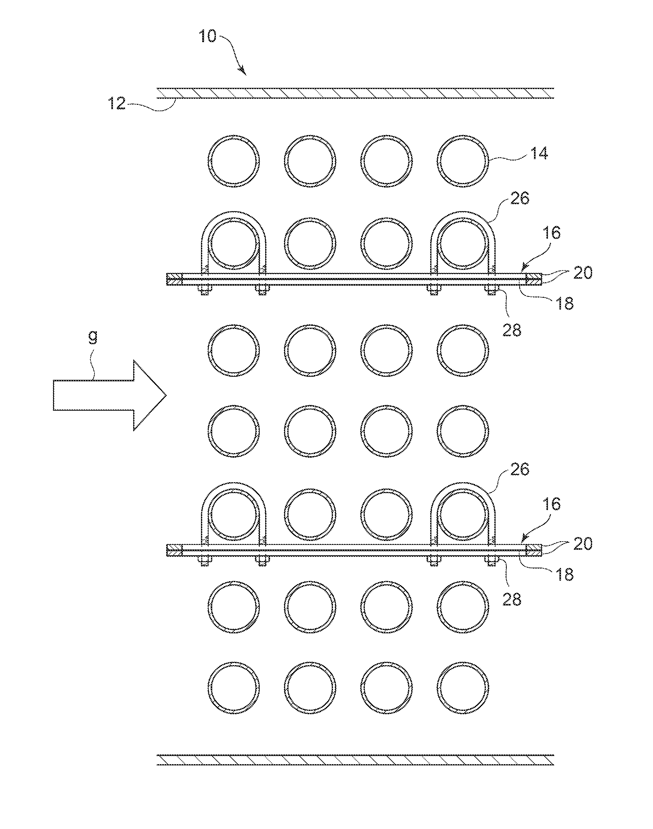
[0034]A heat exchanger according to the first embodiment of the present invention will be described with reference to FIGS. 1 and 3. The present embodiment is an example in which a heat exchanger 10 according to the first embodiment of the present invention is applied to a heat exchanger such as a super-heater, a re-heater, and an economizer, or to a waste-heat recovery boiler, for instance, disposed on a steam boiler incorporated into a thermal power generation plant.

[0035]In FIG. 1, a flow passage of combustion gas g is formed by a duct housing constituting the heat exchanger 10 of the present embodiment. A plurality of hea...


PUM


Abstract

An object is to provide a heat exchanger including a resonance-prevention baffle plate disposed between a plurality of heat transfer tubes, the resonance-prevention baffle plate being obtainable and mountable readily and at lower cost. A heat exchanger 10 disposed in a flow passage of combustion gas of a boiler or the like includes: a plurality of heat transfer tubes 14 disposed in parallel and spaced from one another, an axial direction of each heat transfer tube intersecting with the combustion gas g, inside a duct wall 12 forming the flow passage of the combustion gas g; and a resonance-prevention baffle 16 having a plate shape and disposed along the combustion gas g and between the heat transfer tubes 14, the resonance-prevention baffle including a metal foil sheet 18.

Description

TECHNICAL FIELD[0001]The present invention relates to a heat exchanger disposed on a boiler, for instance, the heat exchanger including a resonance-prevention baffle disposed between a group of heat transfer tubes.BACKGROUND ART[0002]A boiler or the like has a heat exchanger disposed in a duct housing forming a flow passage of combustion gas, the heat exchanger including a super-heater, a re-heater, and an economizer, for example. Such a heat exchanger includes a plurality of heat transfer tubes disposed inside a duct housing, and a medium such as water flowing through the heat transfer tubes is heated by combustion gas to transform into steam. The steam is sent to a steam turbine to be used for power generation. The plurality of heat transfer tubes is disposed so that the axial direction of each heat transfer tube intersects with the flow passage of combustion gas, and spaced in parallel from one another.[0003]The heat transfer tubes are disposed in a direction orthogonal to combus...

Claims


Application Information

Patent Timeline
IPC IPC(8): F28F9/22F22B37/20F28D7/16
CPCF28F9/22F28D7/1615F28F2009/224F28F2265/30F22B37/20F22B37/10F28F9/00
Inventor OKIMOTO, TAKAHIROSUGANUMA, NAOKIKUDO, TOSHIFUMIYAMADA, TETSUYAKITADA, MASASHI
Owner MITSUBISHI HITACHIPOWER SYST LTD
Why Eureka
Try Eureka