Heatsink alignment to printed circuit board

Active Publication Date: 2016-10-06
INTERDIGITAL MADISON PATENT HLDG SAS
View PDF3 Cites 2 Cited by
  • Summary
  • Abstract
  • Description
  • Claims
  • Application Information

AI Technical Summary

Benefits of technology

[0012]The present principles includes a design detail on the perimeter of a heat sink to provide alignment with the printed circuit board during assembly to preve

Problems solved by technology

However, this requirement is becoming increasingly challenging, because set top boxes and the like are required to perform more functions, which require more internal components.
This results in more challenges to appropriately manage the heat which is potentially detrimental, in these devices.
However, these antennae enhance many of the challenges that the designer must face in designing advanced set top boxes and the like.
However, when such larger sizes of the set top box or the like that are associated with the vertical orientation of antennae are not deemed acceptable to the customer's preference, antennae have been oriented horizontally.
This has unfortunately reduced antennae performance.
As such, the trade-off has been that smaller size boxes commensurate with a horizontally oriented antenna have been produced with non-optimal antenna performance.
Additionally, the need for slim devices to include many functionalities and many interior

Method used


Image

  • Heatsink alignment to printed circuit board
  • Heatsink alignment to printed circuit board
  • Heatsink alignment to printed circuit board

Examples


Example

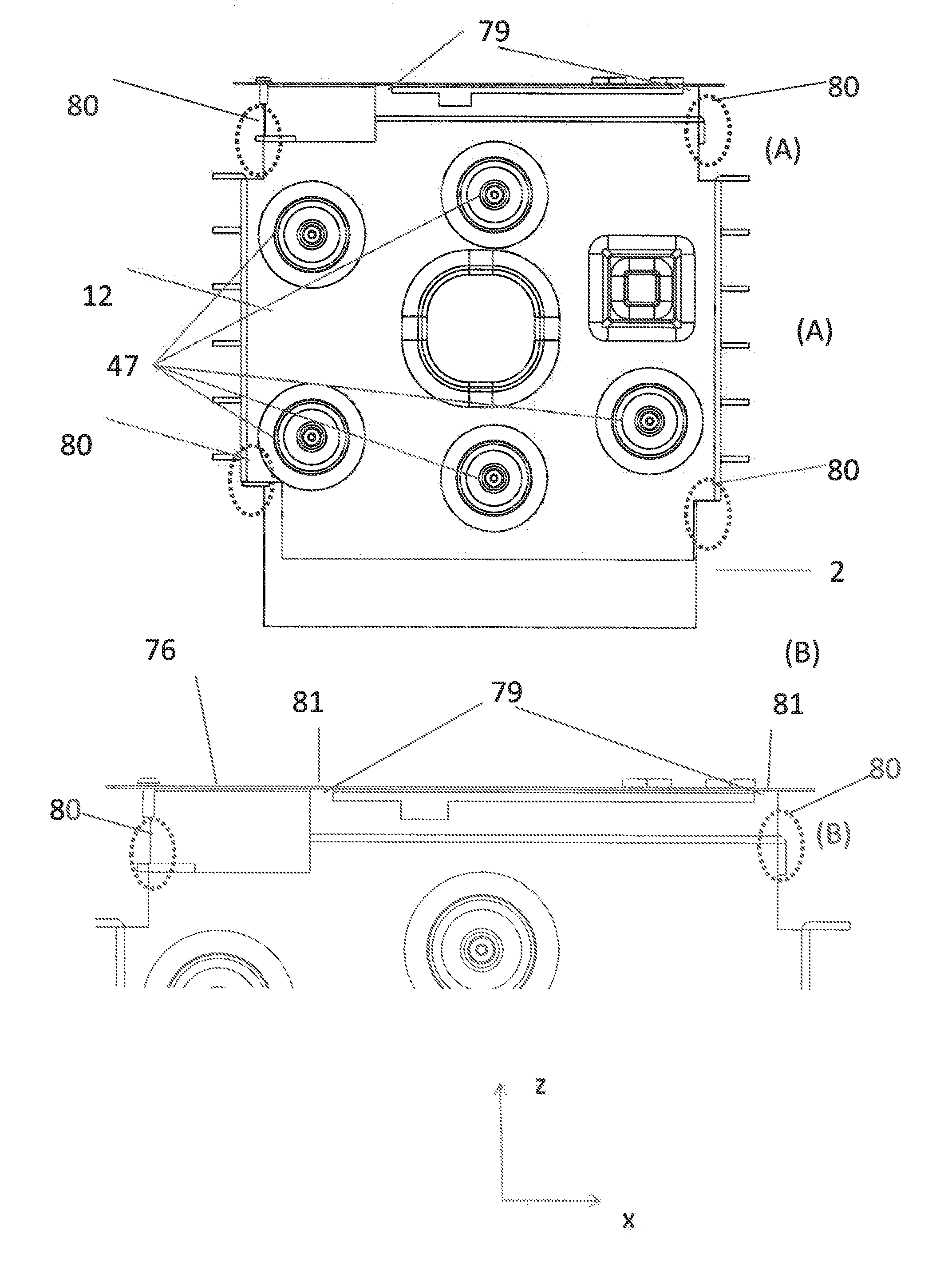
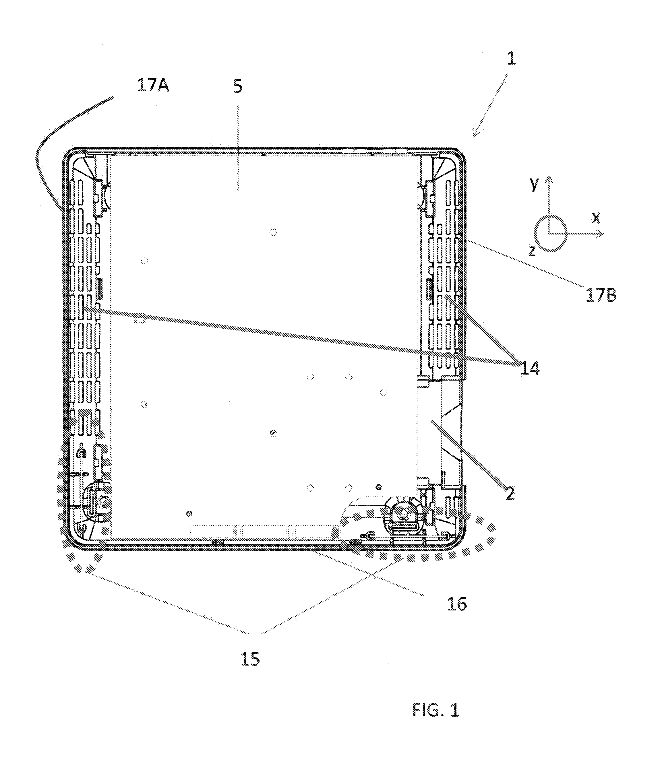
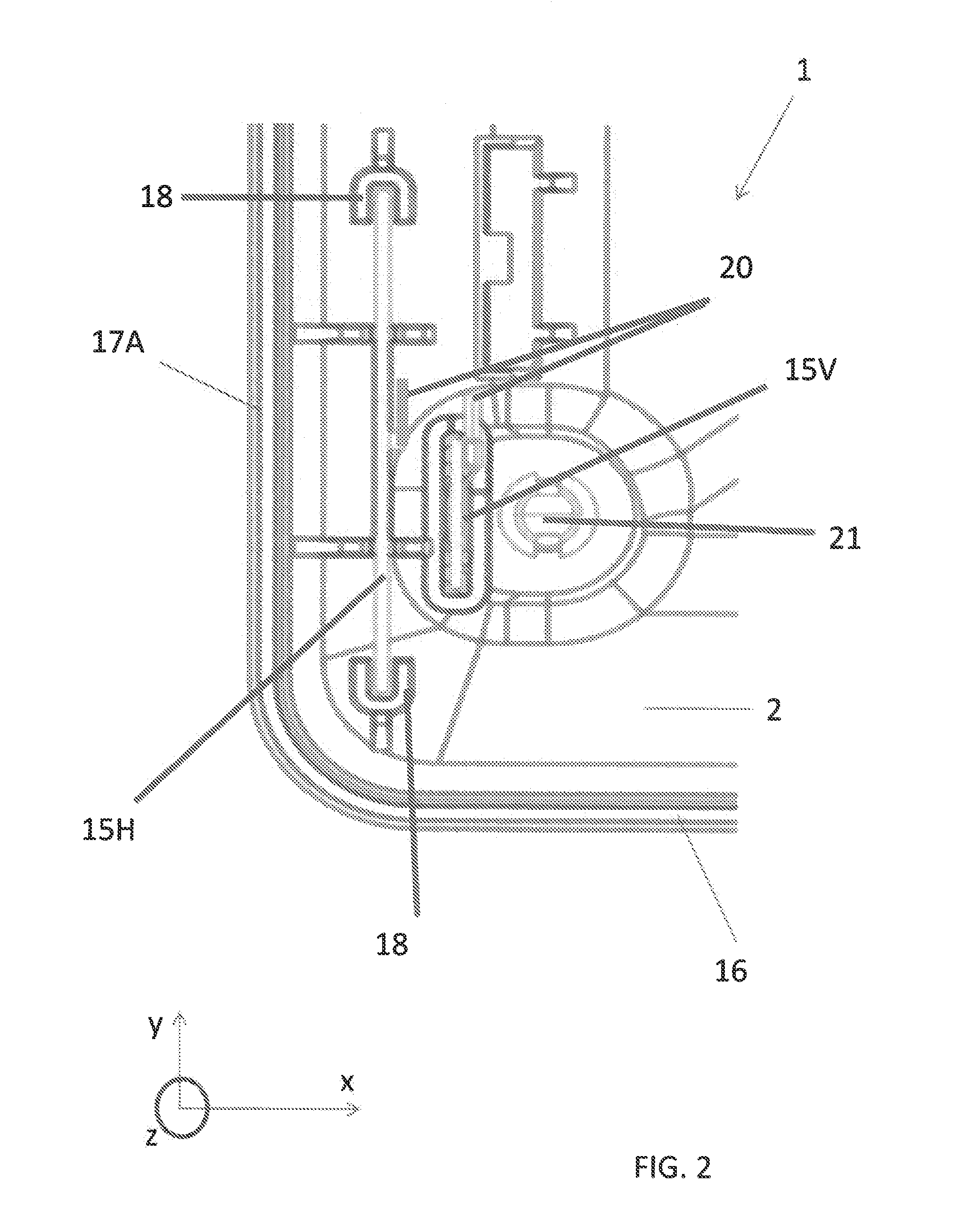
[0035]The present principles is directed to electronics devices such as set top boxes and the like which include antennae and positioning tabs 79 and alignment features 80 on the heat sink 6 as shown in FIGS. 8A and 8B. FIGS. 8A and 8B, which are disassembled views of an electronic device 1 showing a variety of features that can be included in the electronic device 1 according the present principles. As illustrated in the figures, a main circuit board 5 can be housed within a top cover 7 of the device. A thermal barrier (not shown) can be positioned between the circuit board 5 and a bottom frame 2. Alternatively, the circuit board 5 can be considered a circuit board assembly 5 having a thermal barrier attached thereto. A smart card reader (not shown) can be connected to the circuit board 5 through an aperture in the thermal barrier. The device 1 can have internal components such as the smart card reader, the thermal barrier, and a top heat sink 6 contact the circuit board 5 in which...


PUM


Abstract

An electronic device, such as a set top box comprises an enclosure that houses a circuit board having a peripheral edge positioned in the set top box. A heat sink has orientation features on its periphery that contact and orient the circuit board. Further, the heat sink has positioning tabs at a leading edge that contact a control surface on a rear wall of the set top box enclosure and orients the heat sink within the set top box. Antenna assemblies are positioned in corners of the set top box enclosure and adjacent to one of the vertically oriented walls, wherein the antenna assemblies are positioned outside the peripheral edge of the circuit board and the periphery of the heat sink.

Description

CROSS-REFERENCE TO RELATED APPLICATIONS[0001]This application claims the benefit of U.S. Provisional Application Ser. No. 61 / 903,471, filed Nov. 13, 2013 and U.S. Provisional Application Ser. No. 62 / 012545, filed Jun. 16, 2014, which is incorporated by reference herein in its entirety.TECHNICAL FIELD[0002]The present principles relate generally to electronic devices and, more particularly, to electronic devices having a heat sink in the vicinity of a printed circuit board.BACKGROUND ART[0003]Consumer / market preference for set top boxes and the like (such as computers, game consoles, DVD players, CD players, etc.) is to have such devices be small / compact. However, this requirement is becoming increasingly challenging, because set top boxes and the like are required to perform more functions, which require more internal components. This results in more challenges to appropriately manage the heat which is potentially detrimental, in these devices.[0004]Wireless antennae have become one...

Claims


Application Information

Patent Timeline
IPC IPC(8): H05K7/20H05K7/14H05K1/02
CPCH05K7/2039H05K2201/10098H05K7/1427H05K1/0203H05K7/20436H01Q1/02H01Q1/243
Inventor RITTER, DARIN BRADLEYHUNT, MICKEY JAYWILLIAMS, KEVIN MICHAEL
Owner INTERDIGITAL MADISON PATENT HLDG SAS
Why Eureka
Try Eureka