Vehicle lamp

a technology for lamps and vehicles, applied in the field of lamps for vehicles, can solve the problems of plurality of light emitting elements and increase in fabrication costs to such an extent, and achieve the effect of increasing fabrication costs and high functionality

Active Publication Date: 2016-10-13
KOITO MFG CO LTD
View PDF2 Cites 3 Cited by
  • Summary
  • Abstract
  • Description
  • Claims
  • Application Information

AI Technical Summary

Benefits of technology

[0029]According to one or more embodiments of the invention, the light emitted from the light emitting element is guided in the predetermined direction by the first light guiding lens and the second light guiding lens which are formed integrally with the housing, thereby making it possible to ensure the high functionality in relation to shining light without calling for an increase in fabrication costs.

Problems solved by technology

In the vehicle lamp described in Patent Literature 3, however, the light rays emitted from the two light emitting elements are shone in the different directions, and therefore, the fabrication costs are increased to such an extent that the plurality of light emitting elements are provided.

Method used


Image

  • Vehicle lamp
  • Vehicle lamp
  • Vehicle lamp

Examples


Embodiment Construction

[0041]Hereinafter, embodiments of the invention will be described by reference to the accompanying drawings. In embodiments of the invention, numerous specific details are set forth in order to provide a more thorough understanding of the invention. However, it will be apparent to one of ordinary skill in the art that the invention may be practiced without these specific details. In other instances, well-known features have not been described in detail to avoid obscuring the invention.

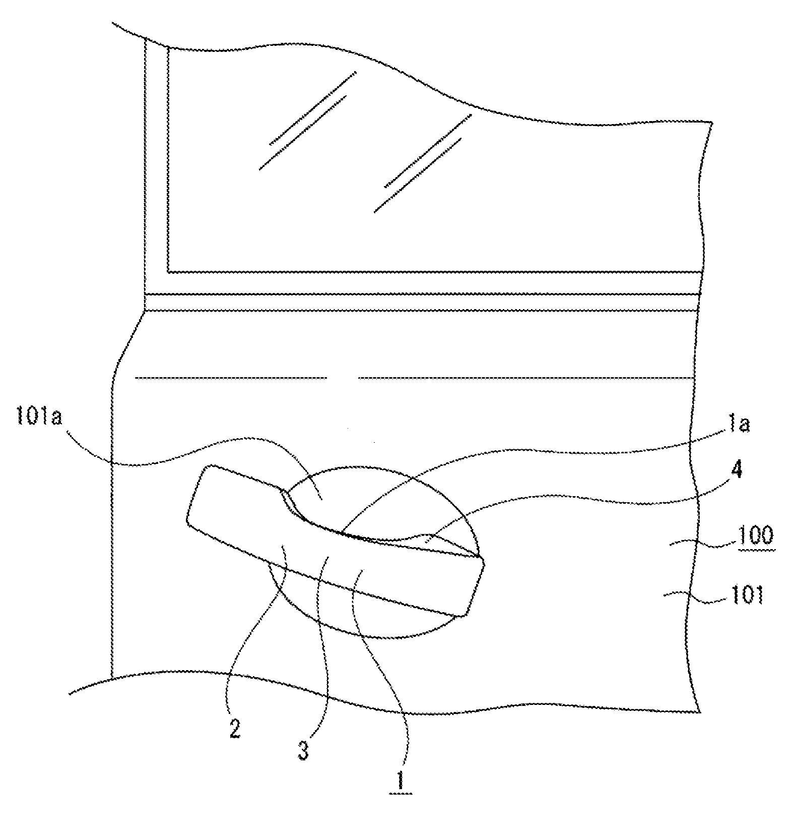
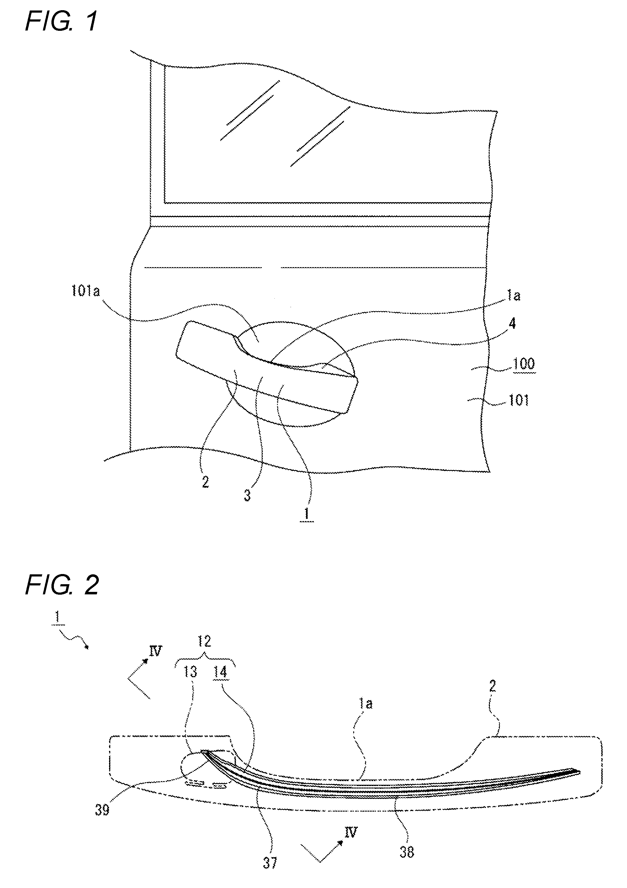
[0042]A vehicle lamp 1 is, for example, a door handle having a shape which extends in a substantially front-to-rear direction and includes a housing 2 and a lamp unit, which will be described later, disposed in an interior of the housing 2 (refer to FIGS. 1 to 3). The vehicle lamp 1 is also used as a hand grip of a door 100 of a vehicle, and a connecting portion, not shown, is provided at a front end portion of the vehicle lamp 1, the front end portion being connected to a door panel 101 (refer to FIG....


PUM


Abstract

A vehicle lamp has a circuit board on which a light emitting element is mounted, a housing for holding the circuit board, a first light guiding lens for guiding part of light emitted from the light emitting element in a predetermined direction, and a second light guiding lens for guiding at least the other part of the light emitted from the light emitting element in the other predetermined direction. The housing, the first light guiding lens and the second light guiding lens are formed integrally.

Description

CROSS-REFERENCE TO RELATED APPLICATIONS[0001]The present application is a national stage application of PCT / JP2014 / 079438 filed Nov. 6, 2014, and claims priority to Japanese Patent Application No. 2013-238806 filed on Nov. 19, 2013, the content of which are incorporated herein by reference in their entirety.BACKGROUND[0002]1. Technical Field[0003]The present invention relates to a technical field of a vehicle lamp including a housing for holding a circuit board on which a light emitting element is mounted.[0004]2. Related ArtPRIOR ART LITERATUREPatent Literature[0005]Patent Literature 1: JP-A-2010-229797[0006]Patent Literature 2: JP-A-2009-133133[0007]Patent Literature 3: JP-A-2006-9279[0008]Some vehicle lamps have a configuration in which a circuit board is held in a housing, and a light emitting element which functions as a light source, for example, is mounted on the circuit board, so that light emitted from the light emitting element is shone in a predetermined direction.[0009]A...

Claims


Application Information

Patent Timeline
Patent Type & Authority Applications(United States)
IPC IPC(8): B60Q1/26F21V23/02F21V19/02F21S8/10F21V5/04
CPCB60Q1/2669F21S48/33F21V5/04F21S48/236B60Q2400/40F21V23/02F21S48/225F21S48/2268F21V19/02
Inventor TAKAHASHI, HARUHITOKAZAOKA, SHIGEHIKO
Owner KOITO MFG CO LTD
Why Eureka
Try Eureka