
Manufacturing method for variator part of torodidal-type continuously variable transmission, variator part of toroidal-type continuously variable transmission and toroidal-type continuously variable transmission

Inactive Publication Date: 2005-08-25
NSK LTD
View PDF4 Cites 3 Cited by
  • Summary
  • Abstract
  • Description
  • Claims
  • Application Information

AI Technical Summary

Benefits of technology

[0016] The present invention has been carried out in view of the above-described problem and an object thereof is to provide a manufacturing method for a variator part of a toroidal-type continuously variable transmission in which a displacement shaft and an outer ring of a thrust rolling bearing are integrated at low cost by restraining an increase in fabrication cost by improving yield of a material and shorting machining time while increasing a strength thereof, a variator part of a toroidal-type continuously variable transmission and a toroidal-type continuously variable transmission.
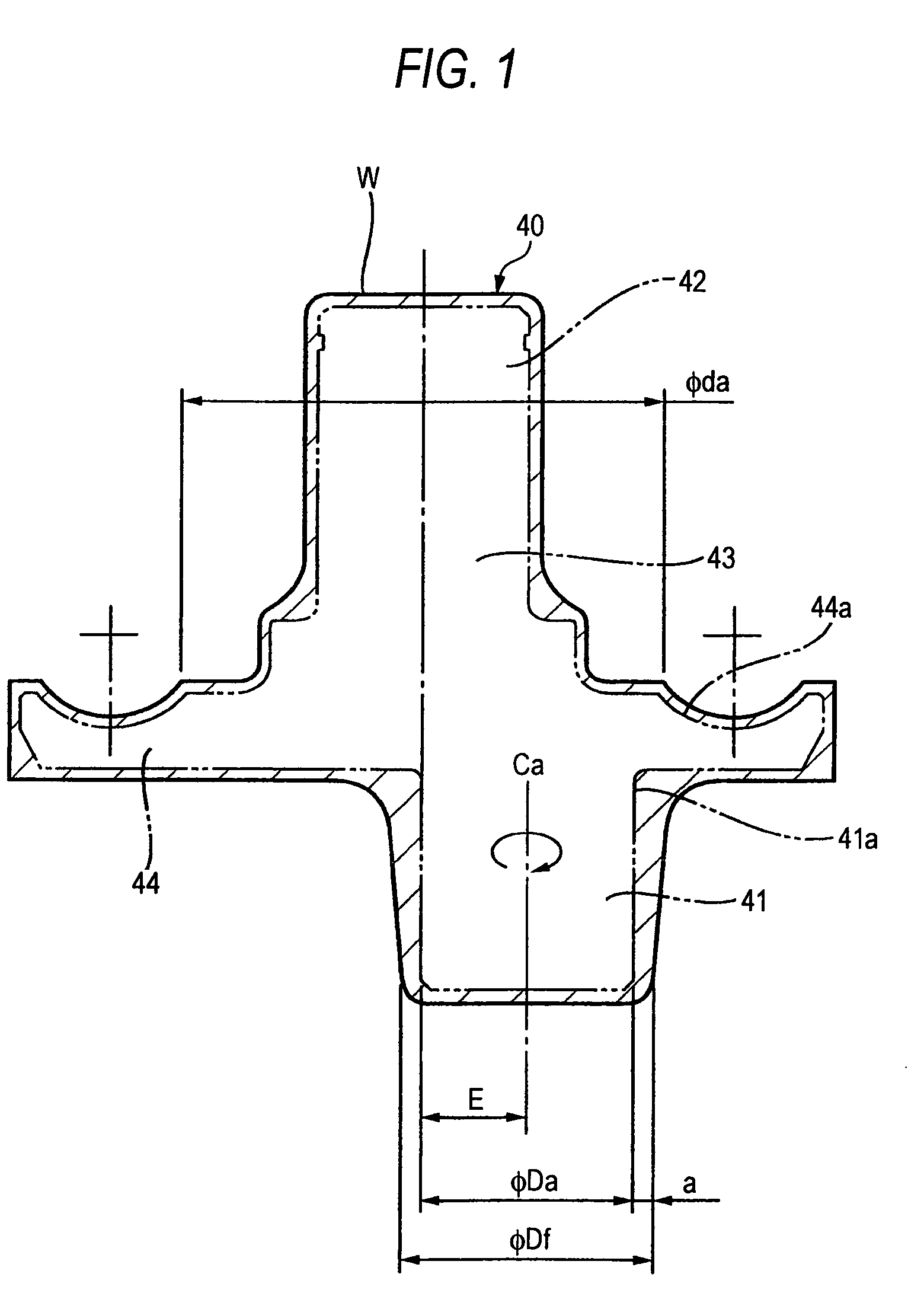
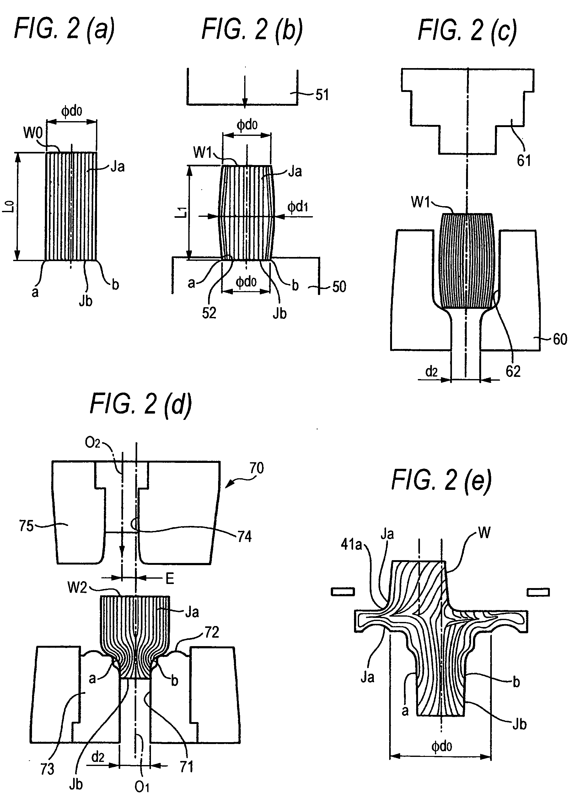
[0068] According to the manufacturing method for a variator part of a toroidal-type continuously variable transmission of the present invention, the support shaft portion formed on an side opposed to the outer ring raceway of the outer ring is forged by the second hole portion of the upper die having the center line at the position eccentric from the center line of the lower die by the predetermined amount. Therefore, the forging material along a desired product shape can be provided. Thereby, a machining margin in turning the support shaft portion can be made to be necessary minimum and machining time can be shortened.
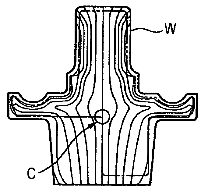
[0069] Further, by forging as described above, at a root portion of the support shaft portion disposed in a direction in which the support shaft portion is eccentric to the pivot shaft portion, a metal flow is formed along a surface thereof. Therefore, even when a stress is applied to the support shaft portion by deforming the outer ring, a strength of the root portion of the support shaft portion can be prevented from being reduced.
[0070] Further, forging is carried out by making an outer diameter of the solid material smaller than the inner diameter of the ring-like raceway groove and making the center line of the solid material coincide with the centerline of the ring-like projected portion forming the outer ring raceway of the outer ring of the solid material. Accordingly, an end flow of an end face of the solid material is not extruded into the outer ring raceway of the outer ring and a metal flow along a surface of the outer ring raceway can be provided. Therefore, even when a repeated stress is operated by relative rotational movement of the thrust ball bearing, the stress can be prevented from being reduced at the outer ring raceway.
[0071] Further, according to the toroidal-type continuously variable transmission of the present invention, the displacement shaft and the outer ring of the thrust rolling bearing are integrated, metal flows at the outer ring raceway of the outer ring and the root portion of the support shaft portion are extended along surfaces thereof. Accordingly, even when the repeated stress is operated by the relative rotational movement of the thrust ball bearing, the strength can be prevented from being reduced at the outer ring raceway and even when the stress is operated at the support shaft portion by deforming the outer ring, the strength can be prevented from being reduced at the root portion of the support shaft portion.

Problems solved by technology

Therefore, there poses a problem that the machining margin is large, yield of the material is poor and working time in machining is also prolonged.
That is, there poses a problem that the metal flow around the support shaft portion 14 of the forging material W of the related art constitutes an end flow substantially over an entire periphery thereof and the strength is reduced.

Method used


Image

  • Manufacturing method for variator part of torodidal-type continuously variable transmission, variator part of toroidal-type continuously variable transmission and toroidal-type continuously variable transmission
  • Manufacturing method for variator part of torodidal-type continuously variable transmission, variator part of toroidal-type continuously variable transmission and toroidal-type continuously variable transmission
  • Manufacturing method for variator part of torodidal-type continuously variable transmission, variator part of toroidal-type continuously variable transmission and toroidal-type continuously variable transmission

Examples


Embodiment Construction

[0081] A manufacturing method for a variator part of a toroidal-type continuously variable transmission, a variator part of a toroidal-type continuously variable transmission and a toroidal-type continuously variable transmission according to the present invention will be explained in details in reference to the drawings as follows. Further a characteristic of the present invention resides in a manufacturing method for a variator part in which a displacement shaft and an outer ring of a thrust rolling bearing are integrated and the variator part. The other structure and operation are similar to those of a toroidal-type continuously variable transmission which has been known in a related art including the above-described structure of the related art. Therefore, an explanation will be omitted or simplified with regard to portions equivalent to those of the structure of the related art and an explanation will be given centering on a characteristic portion of the present invention.

[008...


PUM

PropertyMeasurementUnit
Diameteraaaaaaaaaa
Shapeaaaaaaaaaa

Abstract

A manufacturing method for a variator part of a toroidal-type continuously variable transmission, has the steps of preparing a lower die including a first hole portion and a ring-like projected portion, wherein center lines of the first hole portion and the ring-like projected portion coincide with each other, and an upper die including a second hole portion, wherein a center line of the second hole portion is eccentric from the center line of the first hole portion, mounting a solid material on the lower die so that a center line of the solid material coincides with the center line of the ring-like projected portion, and simultaneously forming the support shaft portion, the outer ring and the pivot shaft portion by pressing the upper die and the lower die so as to approach each other.

Description

[0001] The present invention claims foreign priority to Japanese patent application no. P. 2004-047835, filed on Feb. 24, 2004, the contents of which is incorporated herein by reference. BACKGROUND OF THE INVENTION [0002] 1. Field of the Invention [0003] The present invention relates to a manufacturing method for a variator part of a toroidal-type continuously variable transmission utilized as a transmission of an automobile part or a transmission of an industrial machine or the like, a variator part of a toroidal-type continuously variable transmission and a toroidal-type continuously variable transmission. [0004] 2. Description of the Related Art [0005] In recent years, there has been researched to use a toroidal-type continuously variable transmission as a transmission for an automobile (refer to, for example, Japanese Patent Unexamined Publication No. JP-A-11-51140). As shown in FIG. 3, a toroidal-type continuously variable transmission 1 is provided with a variator part combini...

Claims


Application Information

Patent Timeline
IPC IPC(8): B21J5/02B21J5/12B21K1/00B21K1/12F16C33/64F16H15/38F16H57/021
CPCB21J5/02F16H15/38B21K1/00B21J5/12
Inventor HIRATA, KIYOTAKAIMAI, YOSHISADA
Owner NSK LTD
Learn More