Automatic stop and start control system for an internal combustion engine

Active Publication Date: 2016-10-13
TOYOTA JIDOSHA KK
View PDF0 Cites 26 Cited by
  • Summary
  • Abstract
  • Description
  • Claims
  • Application Information

AI Technical Summary

Benefits of technology

The invention is a control system for a vehicle that stops it from moving when it starts up if the brakes have been switched. The technical effect is that it stops the vehicle from being accidentally moved and ensures safety while driving.

Problems solved by technology

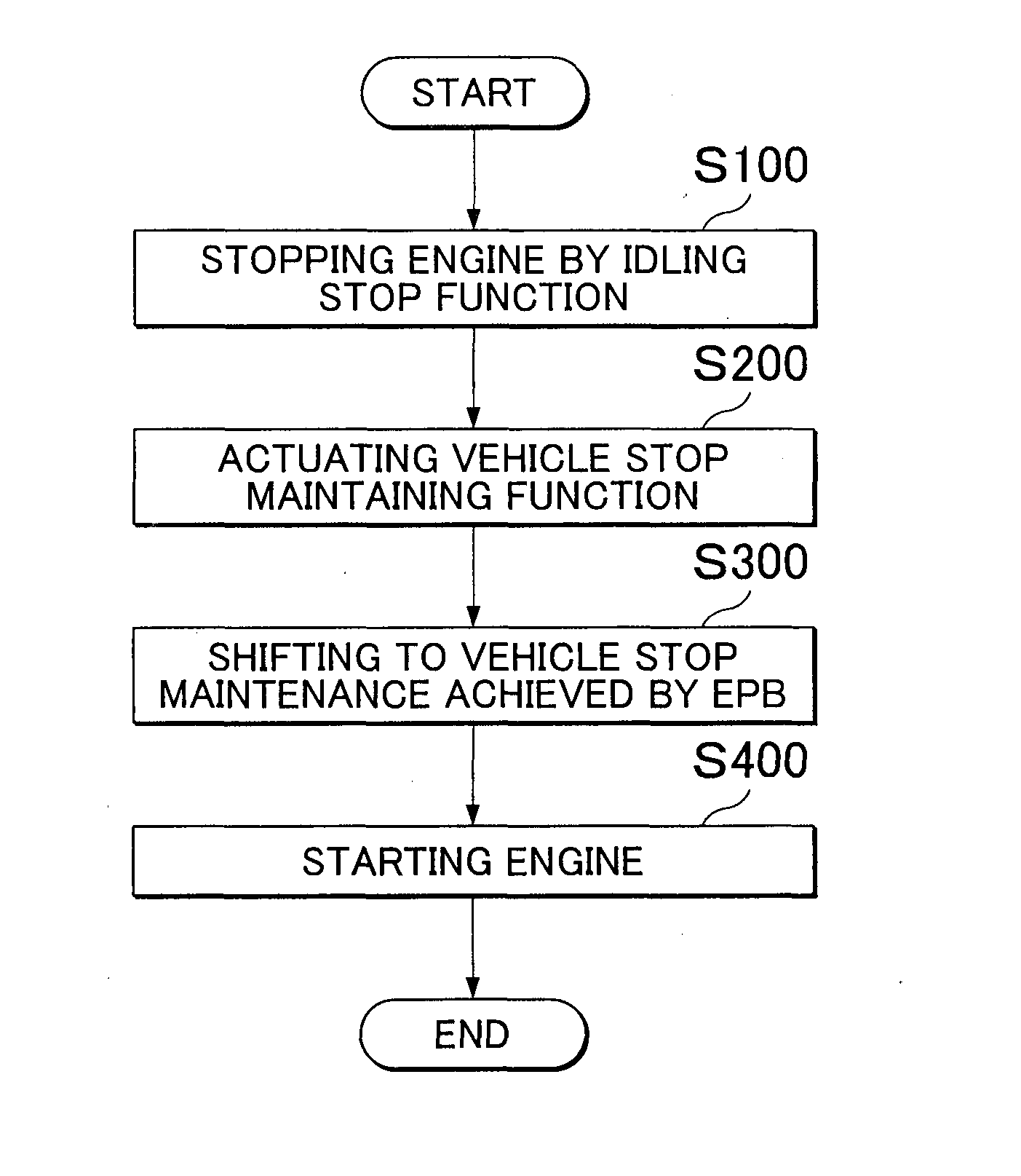
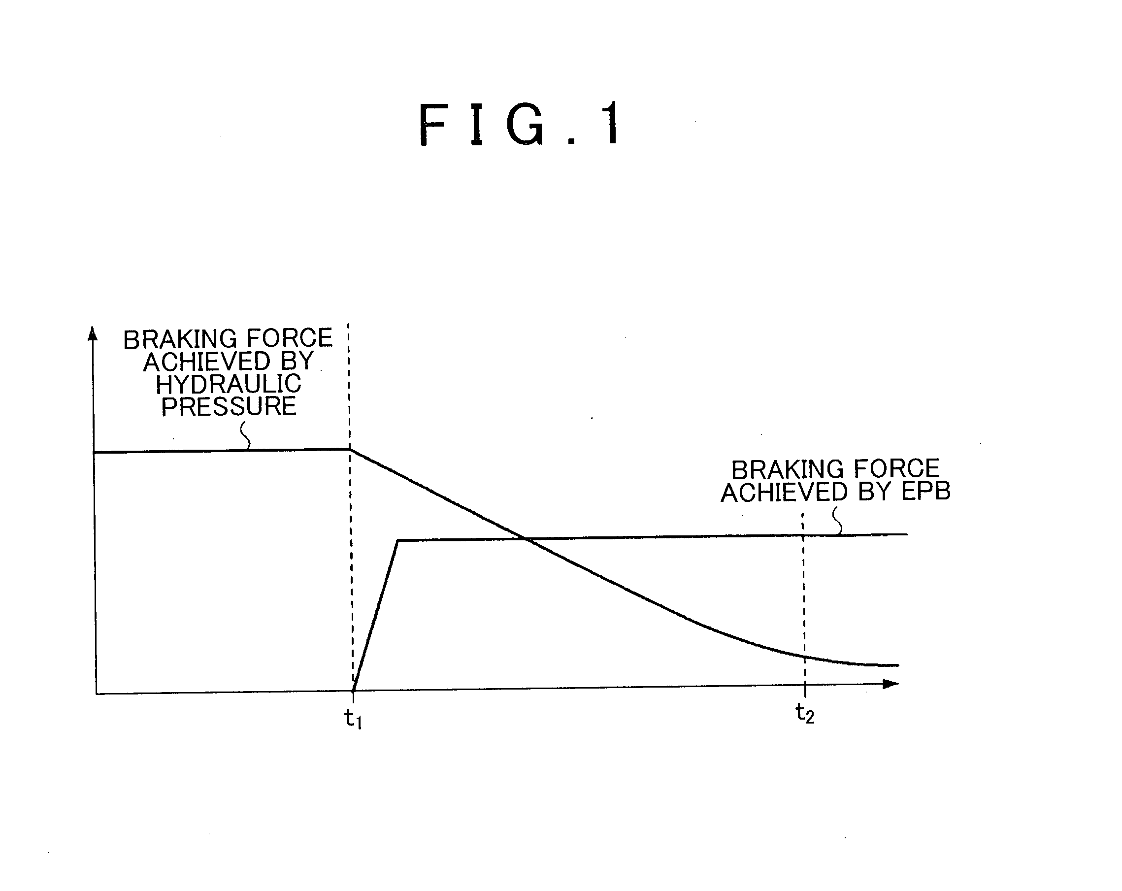
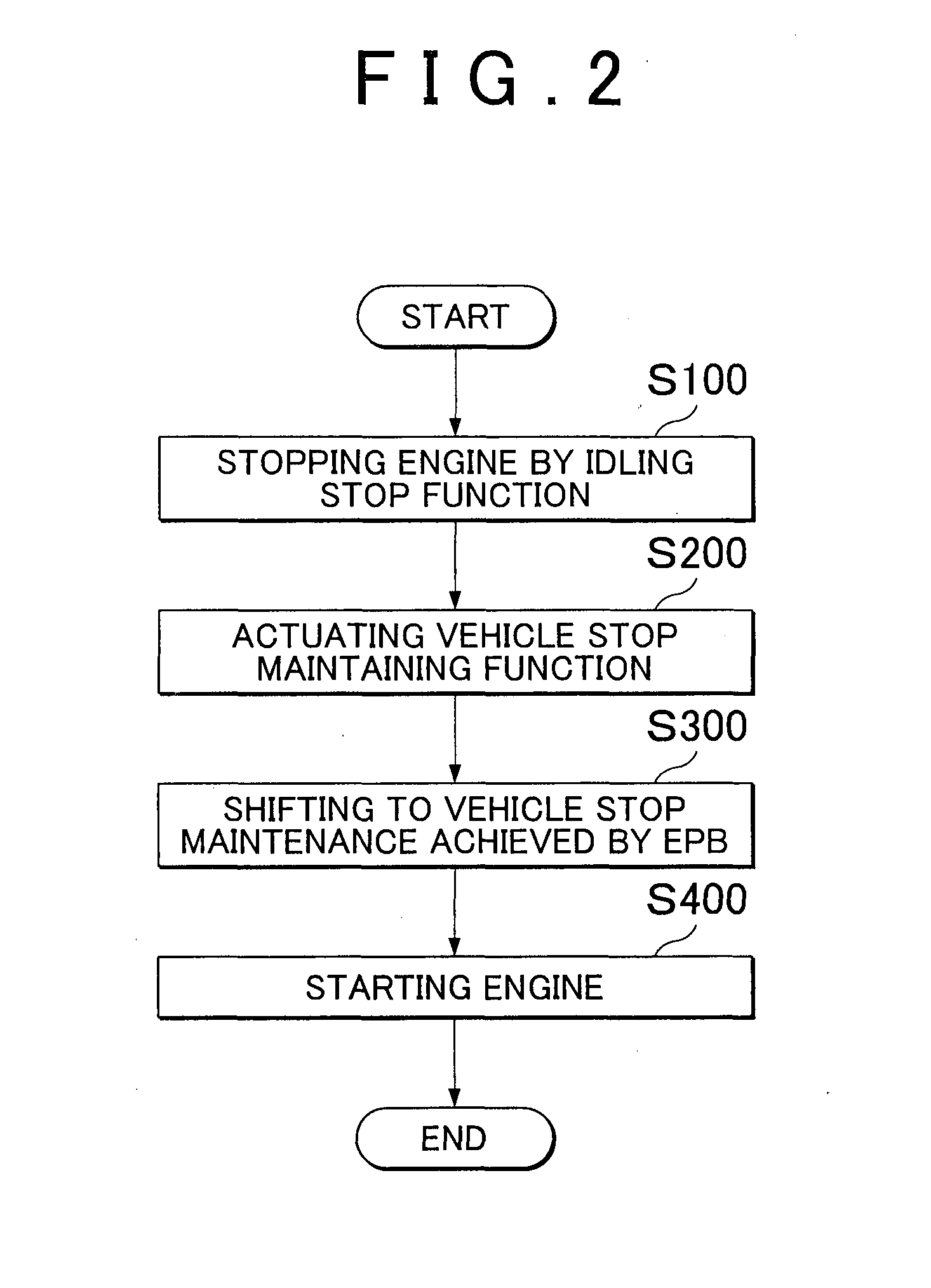
In addition, the braking force by the vehicle stop maintaining function is generated by increasing the hydraulic pressure of wheel cylinders by means of a pump hydraulic pressure, and thus, when this function is in operation for a long time, there may occur a problem that a remaining capacity of a battery decreases.
However, with the braking force being provided by the parking brake, the vehicle may be moved when the engine is started by the idling stop function.
However, because the control on the braking force of the EPB has a slower responsiveness than the control on the braking force provided by the hydraulic pressure, the starting response may be degraded when the release of the EPB and the start of the engine are carried out simultaneously.

Method used


Image

  • Automatic stop and start control system for an internal combustion engine
  • Automatic stop and start control system for an internal combustion engine
  • Automatic stop and start control system for an internal combustion engine

Examples


first embodiment

Structural Example

[0033]FIG. 3 is an exemplary block diagram of the units and function of the control apparatus 100 for a vehicle according to the present embodiment. These units and functions are not necessarily all used for the idling stop function or the vehicle stop maintaining function, and the configuration position and / or shape are only schematically shown. In addition, ECUs and / or sensors are communicatively connected via an on-board network such as CAN (Controller Area Network), or via dedicate lines.

[0034]The battery 15 is a power storage device (secondary battery) capable of charging and discharging. The battery 15 is, for example, a lead storage battery, which supplies power to an electric oil pump 14, a brake hydraulic pump (not shown), a tandem starter 13 and various ECUs (Electronic Control Units). In addition, the battery 15 is charged by the power generated by an alternator 17. The SOC of the battery 15 is monitored by a battery sensor 16.

[0035]The engine 20 is equi...

second embodiment

[0107]In the control apparatus 100 for a vehicle of the first embodiment, in the case where the driver does not sufficiently depress the brake pedal, the engine 20 is started. Hereinafter, in the present embodiment, the control apparatus 100 for a vehicle which starts the engine 20 based on the actual total braking force of the brake ACT 25 and the EPB actuator 30 in the case where the driver does not sufficiently depress the brake pedal will be described. The moving of the vehicle when the engine 20 is started can be more reliably prevented as compared with the first embodiment.

[0108]In the present embodiment, the block views shown in FIG. 3 and FIG. 4 will have the same function in the present embodiment, thus only the main constitution element of the present embodiment will be mainly described.

[0109]FIGS. 8A to 8C are exemplary flowcharts for illustrating an operation sequence of the S&S control part 41. The operation sequence of the BH control part 42 is the same as that in FIGS...


PUM


Abstract

A control apparatus for a vehicle includes: a stop-restart unit that stops an engine if an engine stop condition is satisfied and restarts the engine if a restart condition is satisfied; a first braking force control unit and a second braking force control unit that maintain a braking force for stopping the vehicle; and an engine start unit that starts the engine in the case where a vehicle stop state achieved by the first braking force control unit is switched to a vehicle stop state achieved by the second braking force control unit while the engine is stopped by the stop-restart unit.

Description

BACKGROUND OF THE INVENTION[0001]1. Field of the Invention[0002]The present invention relates to a control apparatus for a vehicle having an idling stop function and a vehicle stop maintaining function.[0003]2. Description of Related Art[0004]An idling stop technology in which an engine is stopped while a vehicle is stopped by a driver's operation on a brake pedal is known. Also, a technology in which the engine that has been stopped by the idling stop technology is restarted when the driver's foot is moved away from the brake pedal is known. The both technologies are collectively called idling stop function, start & stop function, engine-automatically-start-stop function, or the like (hereinafter, simply referred to as “idling stop function”).[0005]In addition, there is also a technology in which the braked state of the vehicle is maintained even though the driver has moved his foot away from the brake pedal while the vehicle is being stopped, which technology is referred to as bra...

Claims


Application Information

Patent Timeline
IPC IPC(8): B60W10/06F02D41/06B60W30/18F02D41/04B60W10/18B60W10/188
CPCB60W10/06B60W10/182B60W10/188F02D41/065B60W30/18109F02D41/042B60W30/18018B60W10/184B60W30/18118F02N11/0822F02N11/0833F02N2200/0803F02N2200/102Y02T10/40B60T7/122
Inventor KATO, HIROKAZU
Owner TOYOTA JIDOSHA KK
Why Eureka
Try Eureka