Magnetic Bearing and Centrifugal Compressor

a technology of magnetic bearings and centrifugal compressors, which is applied in the direction of sliding contact bearings, mechanical equipment, light applications, etc., to achieve the effects of convenient installation and positioning of protection mechanisms, avoiding excessive remanence, and fast separation

Active Publication Date: 2016-10-13
ZHUHAI GREE REFRIGERATION TECH CENT OF ENERGY SAVING & ENVIRONMENTAL PROTECTION
View PDF3 Cites 6 Cited by
  • Summary
  • Abstract
  • Description
  • Claims
  • Application Information

AI Technical Summary

Benefits of technology

[0021]As compared with the prior art, the present disclosure has following beneficial effects: the protection mechanism of the magnetic bearing keeps the thrust plate certain distance away from the iron core. When axial loads are out of control, the thrust plate will not collide with the iron core, avoiding damaging the thrust plate or the iron core. The thrust plate cannot contact with the iron core, thereby avoiding excessive remanence, which may be generated after the power is off, and which may cause the thrust plate unable to be...

Problems solved by technology

However, the magnetic bearing is applied in the fiel...

Method used


Image

  • Magnetic Bearing and Centrifugal Compressor
  • Magnetic Bearing and Centrifugal Compressor
  • Magnetic Bearing and Centrifugal Compressor

Examples


first embodiment

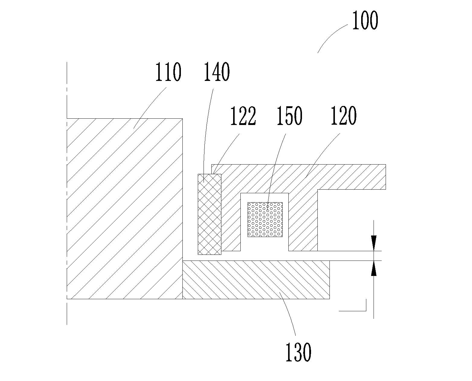
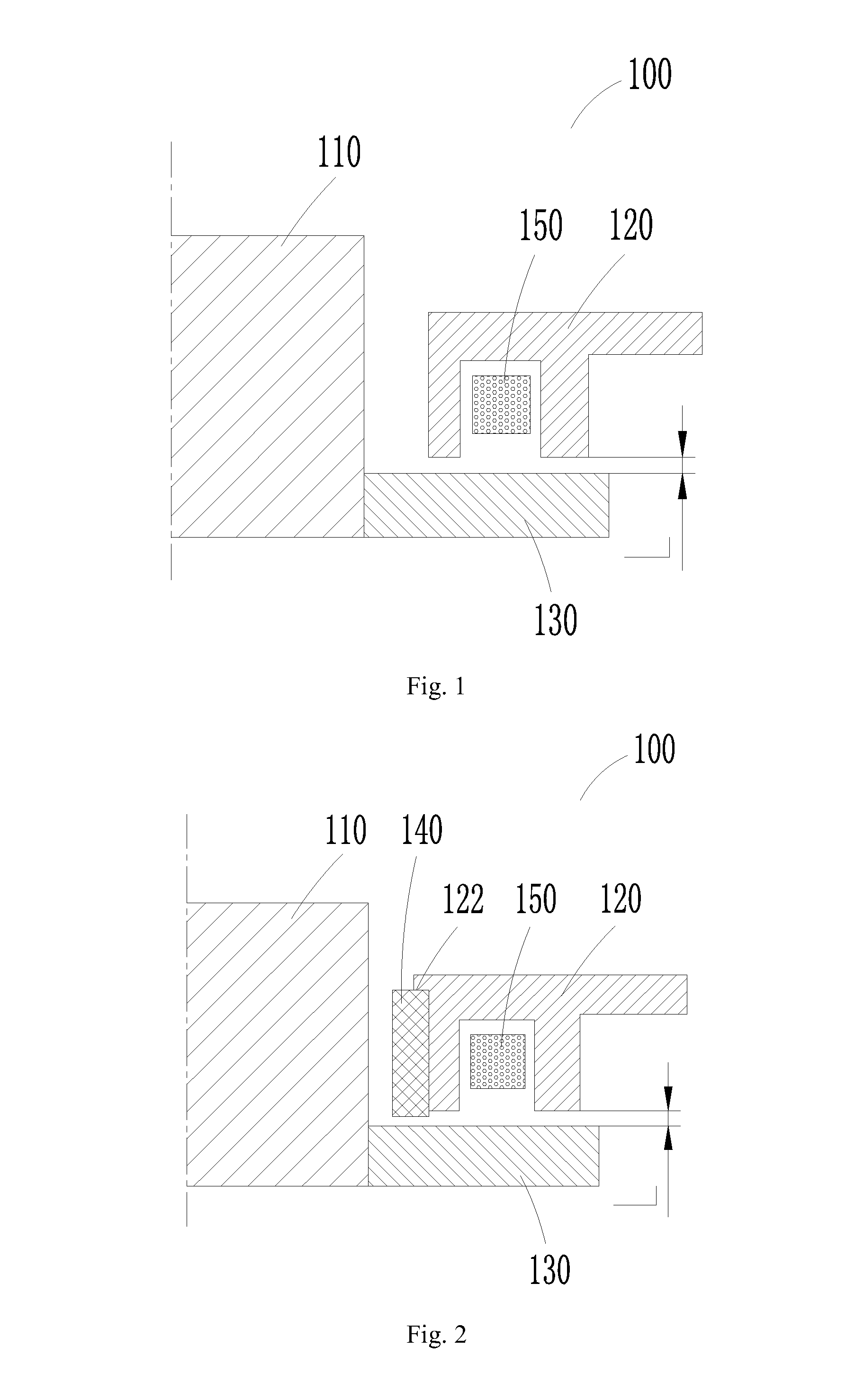
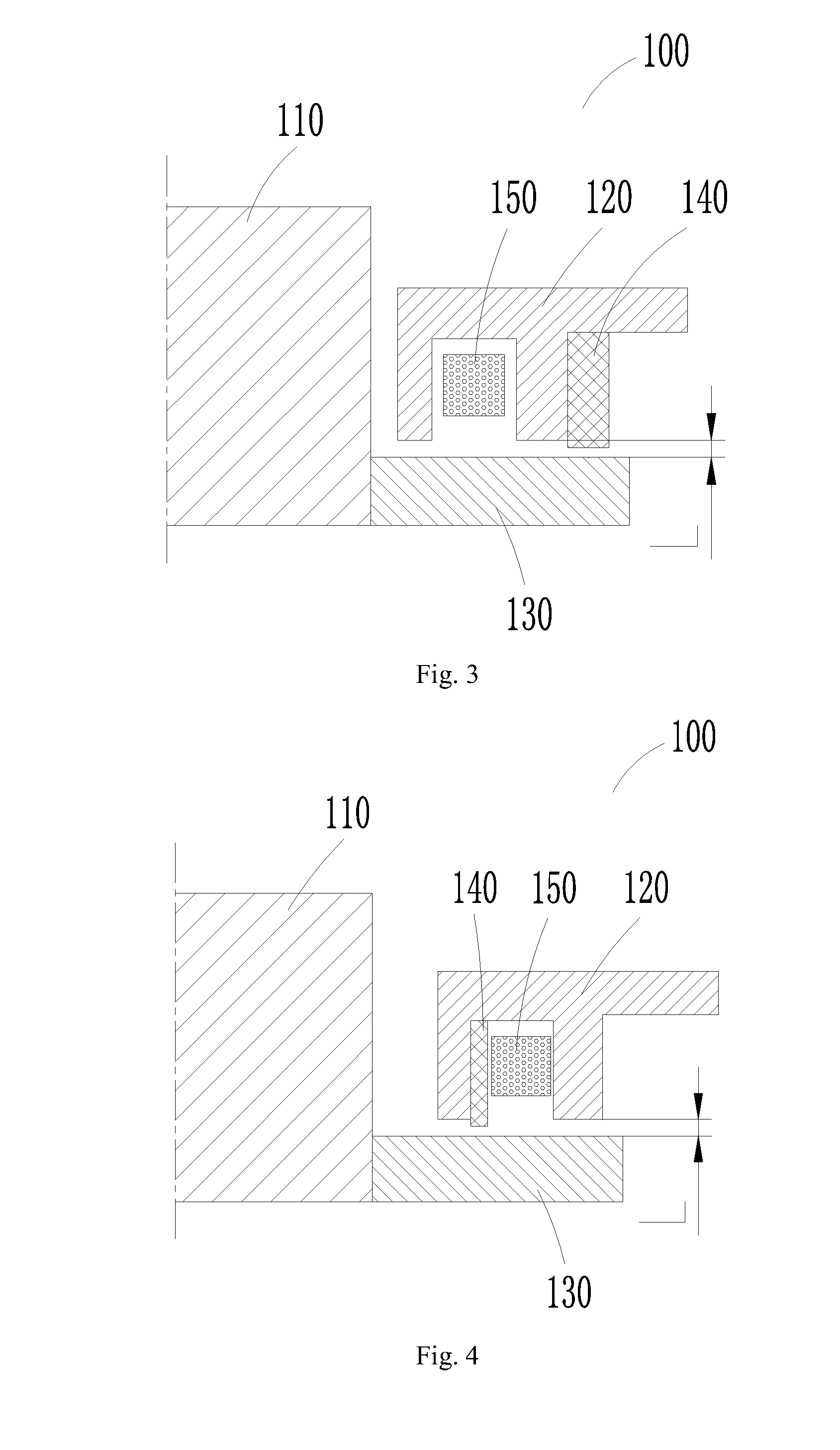
[0029]FIG. 2 is a schematic sectional view of the magnetic bearing according to the present invention. As shown in FIG. 2, the magnetic bearing 100 comprises a revolving shaft 110, an iron core 120, a thrust plate 130, a protection mechanism 140, and coils 150.

[0030]The revolving shaft 110 revolves at a high speed, and the thrust plate 130 is fixed on one end of the revolving shaft 110. The iron core 120 has a winding slot, in which the coils 150 are arranged. The coils 150 are connected to a circuit.

[0031]The protection mechanism 140 is non-ferromagnetic, thus the installation of the protection mechanism 140 will not affect the structure of the magnetic path and takes no effect on the bearing capacity of the magnetic bearing 100. The protection mechanism 140 comprises a support and a coating (not shown). The coating is configured to cover and be fixed on the outer surface of the support. The coating is made of wearable and non-ferromagnetic material.

[0032]The protection mechanism 1...

fourth embodiment

[0044]FIG. 5 is a schematic sectional view of the magnetic bearing according to the present invention. As shown in FIG. 5, the magnetic bearing 100 further comprises a base 160. The iron core 120 is arranged between the thrust plate 130 and the base 160.

[0045]The protection mechanism 140 is fixed on the base 160. Preferably, the protection mechanism 140 is arranged at the intermediate part of the base 160. When the distance between the thrust plate 130 and the iron core 120 is Lmin, the end of the revolving shaft 110 touches the protection mechanism 140.

[0046]As the diameter of the revolving shaft 110 is less than that of the thrust plate 130, the linear velocity of the revolving shaft 110 is relatively smaller. Thereby, when the end of the revolving shaft 110 touches the protection mechanism 140, the friction force acting on the protection mechanism 140 is relatively smaller. The nearer the protection mechanism 140 is to the center of the base 160, the smaller the friction force is...


PUM


Abstract

Disclosed are a magnetic bearing and a centrifugal compressor. The magnetic bearing comprises a revolving shaft (110) and an electromagnetic component, wherein the electromagnetic component is arranged around an outer periphery of the revolving shaft (110), and a gap is formed between the electromagnetic component and the revolving shaft (110) for adjusting a position of the revolving shaft (110). The electromagnetic component comprises an iron core (120) with a winding slot, and coils (150). The coils (150) are arranged in the winding slot. The magnetic bearing (100) also comprises a protection mechanism (140), which is configured to prevent the revolving shaft (110) from colliding with the electromagnetic component, thereby achieving the purpose of axially protecting the magnetic bearing (100). The centrifugal compressor comprises the magnetic bearing (100), thereby obtaining axial protection and prolonging service life.

Description

CROSS REFERENCE TO RELATED APPLICATIONS[0001]This application claims the benefit of priority of Chinese Patent Application No. 201310419738.7, filed on Sep. 13, 2013, entitled “Magnetic Bearing and Centrifugal Compressor”, the entire contents of which are incorporated herein by reference.TECHNICAL FIELD[0002]The present disclosure relates to a magnetic bearing and a centrifugal compressor, more especially, to a magnetic bearing having a protection mechanism, and a centrifugal compressor.BACKGROUND[0003]When a current is applied to the winding of a magnetic bearing, the magnetic field generated forms a loop between the iron core and the thrust plate, forming electromagnetic force between the iron core and the thrust plate; the air gap distance between the revolving shaft and the stator is measured by a displacement sensor, and the electromagnetic force is regulated through adjusting the current in the winding, so as to control the size of the air gap between the revolving shaft and t...

Claims


Application Information

Patent Timeline
IPC IPC(8): F16C32/04F16C17/04
CPCF16C32/0476F16C2362/52F16C32/0442F16C17/04F16C17/08F16C39/02F16C2360/44
Inventor HUANG, HUIHU, YUSHENGCHEN, DONGSUOZHANG, FANGZHANG, XIAOBOLIU, JIANNING
Owner ZHUHAI GREE REFRIGERATION TECH CENT OF ENERGY SAVING & ENVIRONMENTAL PROTECTION
Why Eureka
Try Eureka