Integrated grab bar and navigation controller

a navigation controller and integrated technology, applied in the direction of steering initiation, mechanical control devices, instruments, etc., can solve the problems of not being able to use the same, not being weatherproof, and being unable to effectively use the same, so as to achieve reliable navigation control, easy thumb-actuated navigation control, and strong grip

Active Publication Date: 2016-10-20
STEVEN FOX I
View PDF1 Cites 10 Cited by
  • Summary
  • Abstract
  • Description
  • Claims
  • Application Information

AI Technical Summary

Benefits of technology

[0009]The present invention is intended to overcome the drawbacks of the prior attempts. In accordance with exemplary embodiments, a rigidly fixed grip member and control head maintains the necessary spacial relationship between the thumb of the gripping hand and the primary control switches needed for navigation while under weigh, and maintain a strong grip on the grip member and / or control head acting as a grab bar with easy thumb-actuated navigation control regardless of the motion of the vehicle. In the case of a watercraft, in particular, a small watercraft such as a dingy, a waggling joystick is a navigation hazard in a rough seaway whereas the present invention provides convenient thumb controls on a fixed grip maintain reliable navigation control while enabling a robust and steady grab bar to resist unwanted movement of the user's body.
[0010]In accordance with an embodiment of the present invention, a navigation controller for a watercraft is provided. A force transfer member transfers an applied force to a structural member, such as the floor, transom, engine mount, armrest or other structure member of a watercraft. A mount is rigidly fix to the force transfer member for transferring the applied force to the force transfer member. A grip member and control head are configured and dimensioned to be grabbed by a hand of a user and transfer the force to the mount. The grip member is rigidly mounted to the mount for transferring the applied force to the mount. The grip member is engagable by fingers on the hand of the user for providing a grab bar to the user to resist movement of the body of the user caused by the applied force. The applied force is transferred through the hand of the user to the grip member to the mount to the force transfer member to the structural member to dissipate the applied force in resisting excessive movement of the body of the user caused by the applied force. Control switches generate control output signals for controlling the operation of the watercraft. A control plate supports the control switches and is disposed on the control head near to the grip member and positioned, configured and dimensioned relative to the grip member to enable a thumb of the user to engage with one or more of the control switches while the fingers remain engaged with the grip member and / or control head so that the resistance of the applied force to keep the user steady does not cause an unintended activation of one or more of the control switches. A tactile location indicator is disposed on the control plate provides easy and rapid location indication of the thumb's position relative to the control switches by haptic feedback.
[0014]Control switches are provided for generating control output signals for controlling the navigation of the watercraft. A control plate supports the control switches. The control plate is disposed near to the grip member and positioned, configured and dimensioned relative to the grip member to enable a thumb of the user to engage with one or more of the control switches while the fingers remain engaged with the grip member. Unlike a conventional joystick or steering wheel used for navigation control of a vehicle, such as a watercraft, in accordance with the present invention the grip member and control head are rigidly fixed. The fingers of the user remain engaged with the grip member, and the grip member and control head are rigidly mounted during operation of the switches so that the resistance of the applied force to keep the user steady does not cause a unintended activation of one or more of the control switches, while the user's grip on the grip member and / or control head is still effective to steady the user against the applied force.
[0016]In accordance with another aspect of the invention, a navigation controller is provided for a vehicle, such as a watercraft. A force transfer member transfers an applied force to a structural member of a watercraft. A mount is rigidly fix to the force transfer member for transferring the applied force to the force transfer member. A first grip member and control head are configured and dimensioned to be grabbed by a right hand of a user and a second grip member and control head are configured and dimensioned to be grabbed by a left hand of the user. The grip members are both rigidly mounted to the mount for transferring the applied force to the mount and a yoke may be provided rigidly fixing the two grip members to each other. The right grip member and control head are engagable by fingers on the right hand of the user for providing a grab bar to the user to resist movement of the body of the user caused by the applied force. The left grip member and control head are engagable by fingers on the left hand of the user for providing a grab bar to the user to resist movement of the body of the user caused by the applied force. The applied force is transferred through either or both the right hand and the left hand of the user to the respective grip member to the mount to the force transfer member to the structural member to dissipate the applied force in resisting excessive movement of the body of the user caused by the applied force. Control switches generate control output signals for controlling the navigation of the watercraft. A control plate supports the control switches and is disposed near to one of the right grip member and the left grip member and positioned, configured and dimensioned relative to the respective grip member to enable a thumb of the user to engage with one or more of the control switches while the fingers remain engaged with the respective grip member. A tactile location indicator is disposed on the control plate to facilitate quick locating of a particular control switch by the thumb while the fingers remain engaged with the grip member.

Problems solved by technology

Conventional joysticks, especially those used for controlling boats on the water, are typically not weatherproof even though they are inherently exposed to high humidity, corrosive and wet environments.
In particularly, because a typical navigation joystick must pivot in order to perform its intended function, it is not possible to utilize the same hand used to control the navigation of the watercraft and to use the joystick as an effective grab bar to steady the user against movement caused by an applied force, such as that resulting from a wave or motion of the watercraft.
Inherent in the use of a watercraft is bumping and jostling of the user's body during navigation control of the watercraft.
A conventional joystick requires the stick to be pivoted during use, so it is not effective as a grab bar.
Likewise, a grab bar is not effective for use as a conventional pivoting joystick.

Method used


Image

  • Integrated grab bar and navigation controller
  • Integrated grab bar and navigation controller
  • Integrated grab bar and navigation controller

Examples


Embodiment Construction

[0048]For purposes of promoting an understanding of the principles of the invention, reference will now be made to the embodiments illustrated in the drawings and specific language will be used to describe the same. It will nevertheless be understood that no limitation of the scope of the invention is thereby intended, there being contemplated such alterations and modifications of the illustrated device, and such further applications of the principles of the invention as disclosed herein, as would normally occur to one skilled in the art to which the invention pertains.

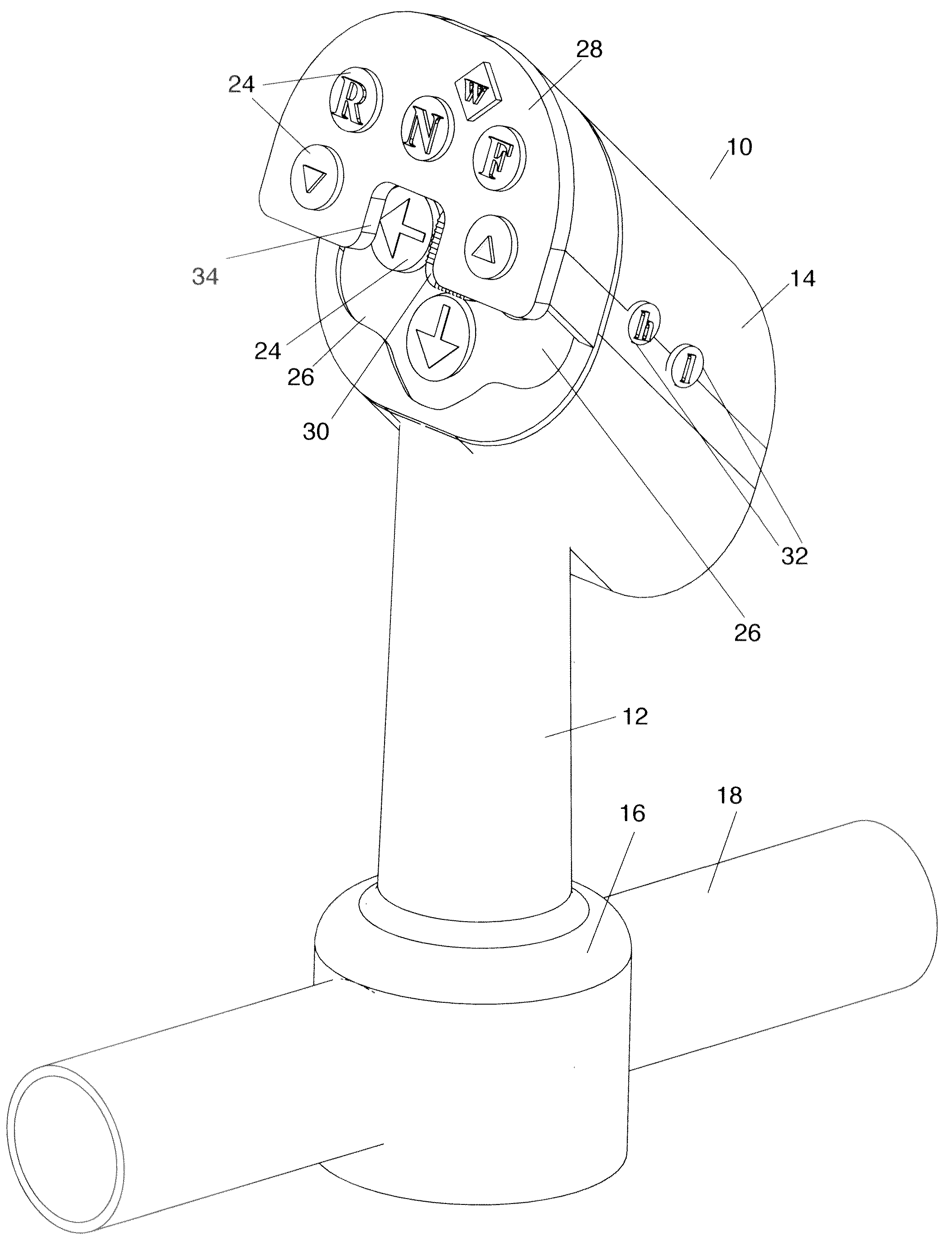
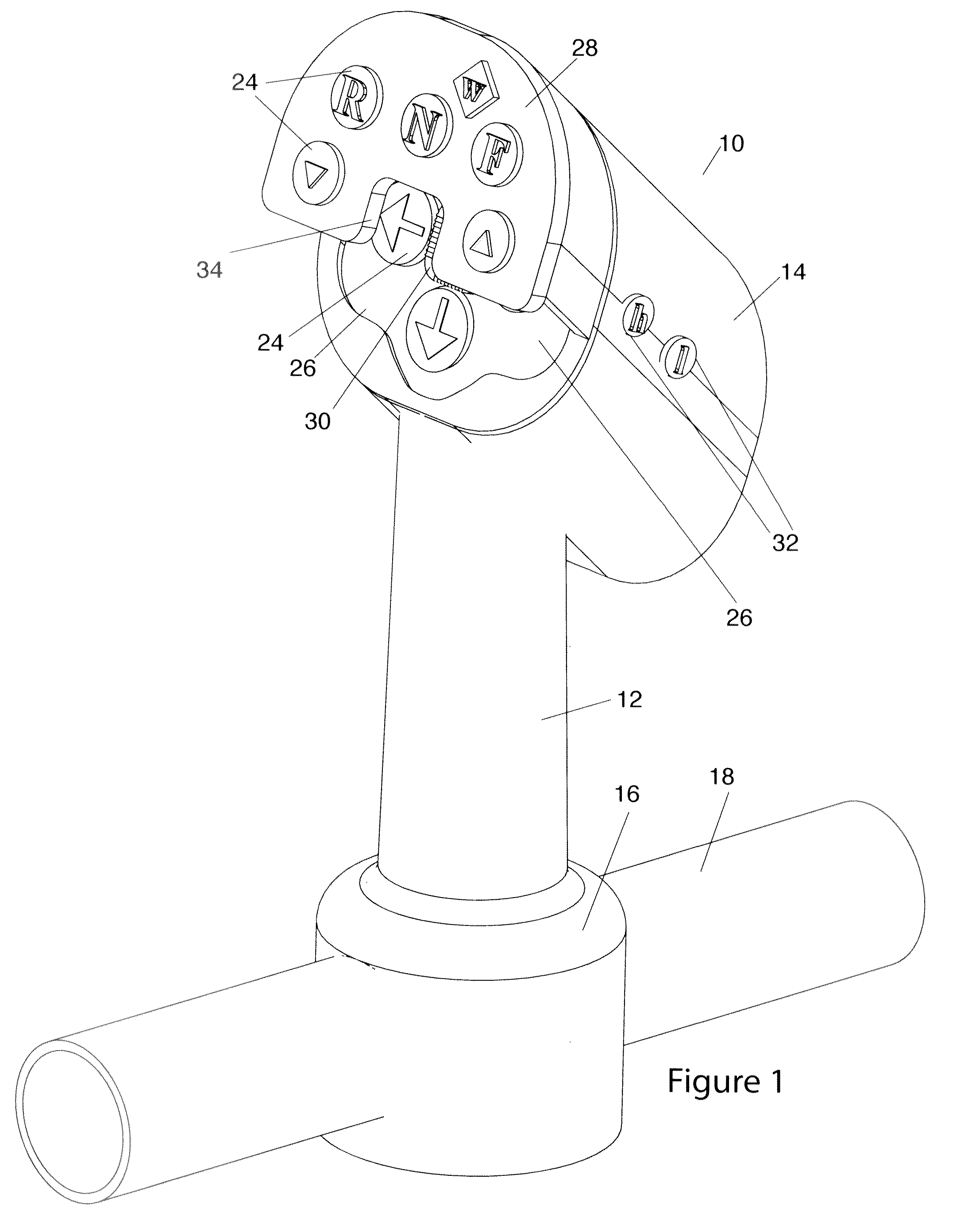
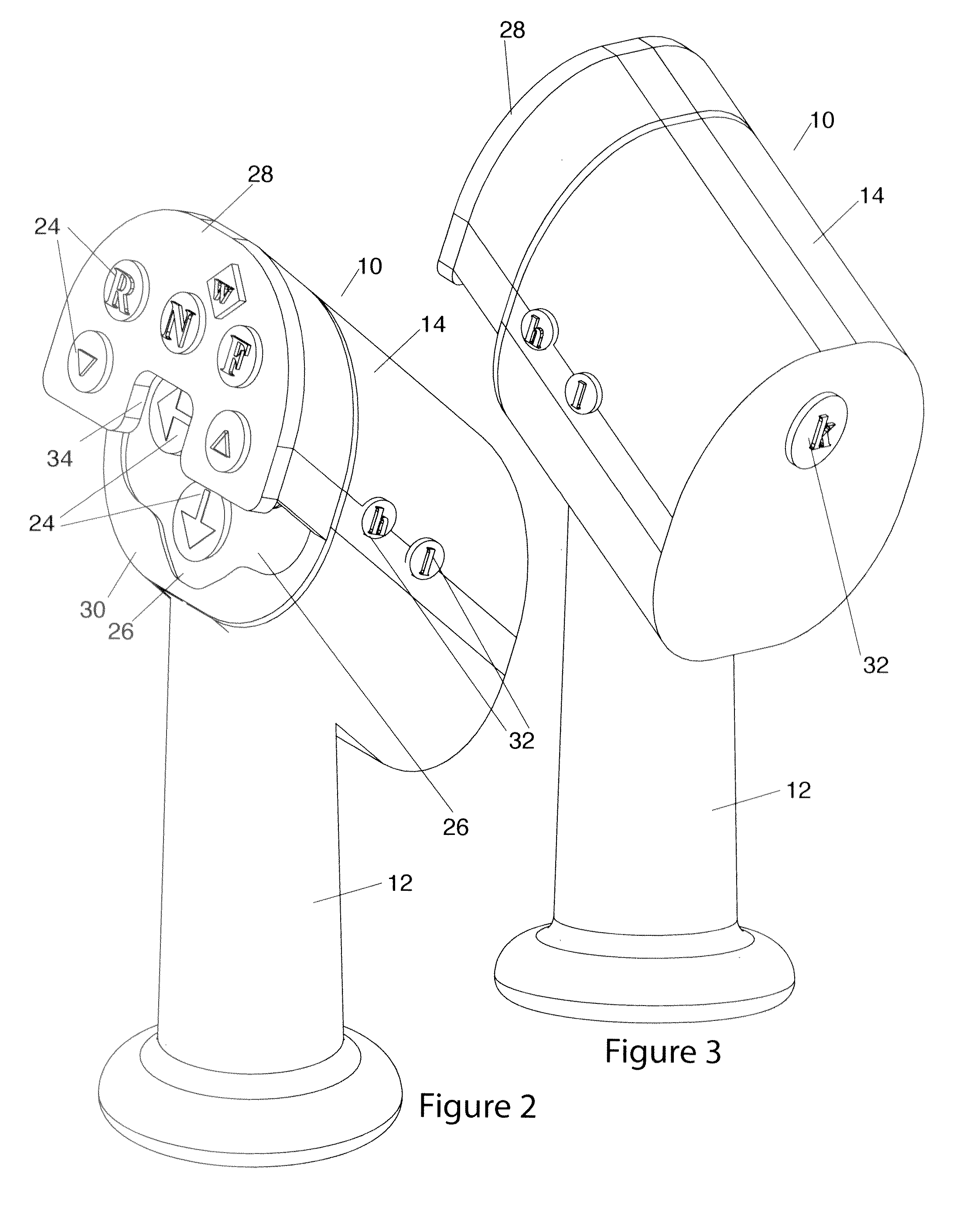
[0049]A conventional joystick has a number of drawbacks, especially when used for the operation of a vehicle, such as a watercraft. Inherent in the use of a watercraft is bumping and jostling of the user's body during navigation control of the watercraft. Since a conventional joystick requires the stick to be pivoted during use, it is not effective as a grab bar. Likewise, since a grab bar has to remain rigidly fixed ...


PUM


Abstract

A navigation controller for a watercraft enables an operator to safely control the vessel even when in rough seas. A grip member and control head act as an integrated grab bar to be grabbed by a hand of a user and transfer the force to a mount. The grip member is engagable by fingers on the hand of the user for providing a grab bar to the user to resist movement of the body of the user caused by the applied force. The applied force is transferred through the hand of the user to the grip member to the mount to a force transfer member to a structural member to dissipate the applied force in resisting excessive movement of the body of the user caused by the applied force. A navigation controller includes control switches for controlling the operation of the watercraft. A control plate supports the control switches and the control plate with the control switches is configured and dimensioned relative to the grip member to enable a thumb of the user to engage with one or more of the control switches while the fingers remain engaged with the grip member so that the resistance of the applied force to keep the user steady does not cause a unintended activation of one or more of the control switches. A tactile location indicator is disposed on the control plate to provide easy and rapid location indication by haptic feedback. The control switches may include piezo switches to allow use in a severe marine environment that may include prolonged deep immersion, and powerful and prolonged salt spray and pressure washing, enduring conditions that would render a conventional marine joystick inoperable.

Description

CROSS REFERENCE TO RELATED APPLICATION[0001]This application is a U.S. Utility Patent Application of U.S. Provisional Patent Application No. 61 / 981747, filed Apr. 19, 2014, the disclosure of which is incorporated herein in its entirety.TECHNICAL FIELD[0002]The present invention relates to a navigation controller for a moving vehicle. More particularly, the present invention relates to an integrated grab bar and navigation controller for a moving vehicle such as a watercraft.BACKGROUND OF THE INVENTION[0003]A conventional joystick is a user input device that includes a stick that pivots on a base and outputs control signals that indicate the angle and / or direction of the stick. A joystick is also known as the control column and has been the principal control device for many civilian and military aircraft, either as a center stick or side stick. Conventional joysticks are also used for controlling heavy equipment, remote control of unmanned vehicles, wheelchairs, surveillance cameras,...

Claims


Application Information

Patent Timeline
Patent Type & Authority Applications(United States)
IPC IPC(8): B63H25/02B63B17/00G05G1/58B63B17/04G06F3/01G05G13/00
CPCB63H25/02G06F3/016G05G13/00B63H2025/026B63B17/04B63B17/0081G06F2203/015G05G1/58B63H21/213G05G1/01
Inventor STEVEN, FOX I
Owner STEVEN FOX I
Why Eureka
Try Eureka