Autonomous Glow Driver For Radio Controlled Engines

a radio controlled engine and glow driver technology, applied in the direction of engine starters, incandescent ignition for engines, machines/engines, etc., can solve the problems of difficult initial start of glow engines, engine failure to start successfully, and insufficient combustion chamber temperature, etc., to reduce movement, reduce noise, and reduce the effect of friction

Active Publication Date: 2016-10-20
DEMMONS SHELDON J
View PDF13 Cites 8 Cited by
  • Summary
  • Abstract
  • Description
  • Claims
  • Application Information

AI Technical Summary

Benefits of technology

[0016]The connector also includes an electrically conductive second insert. The second insert has a tube section with internal threads on an inner surface of the tube section. The tube section is inserted into the central opening of the housing and fixed therein. Next, an electrically conductive threaded member having a threaded shaft engages the internal threads of the second insert. The threaded shaft has a bottom having a bore. The bore is designed to receive a stem end of a glow plug. In use, rotating the threaded member imparts a downwards pressure through the glow plug onto the bottom lip of the housing to hold t...

Problems solved by technology

However, it can be a particularly difficult task to initially start glow engines when the glow element and the combustion chamber is cold.
One issue, however, relates to when starting has actually occurred.
If the glow driver is removed too early, the temperature of the combustion chamber may not be sufficiently hot and the engine may not start successfully.
This is particularly important for model planes or model boats, where losing power could cause the vehicle to crash or become stranded in a body of water.
For example, if the engine is idling for an extended period of time, such as during the landing portion of the flight, if the ambient temperature drops, or if an excessive amount of fuel enters the system and causes rapid cooling or flooding to occur.
In that situation, it is unlikely that engine will maintain ignition ...

Method used


Image

  • Autonomous Glow Driver For Radio Controlled Engines
  • Autonomous Glow Driver For Radio Controlled Engines
  • Autonomous Glow Driver For Radio Controlled Engines

Examples


Embodiment Construction

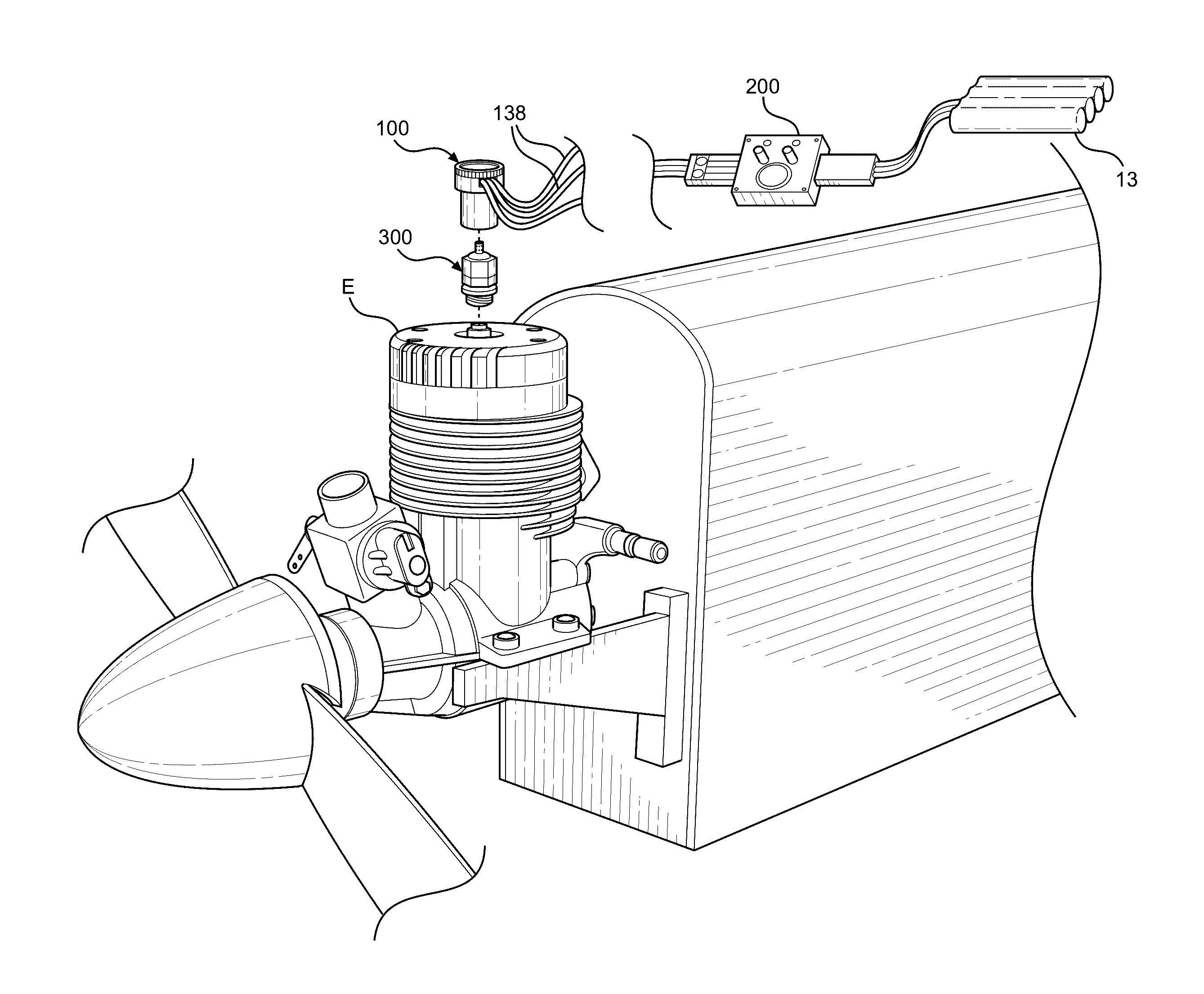
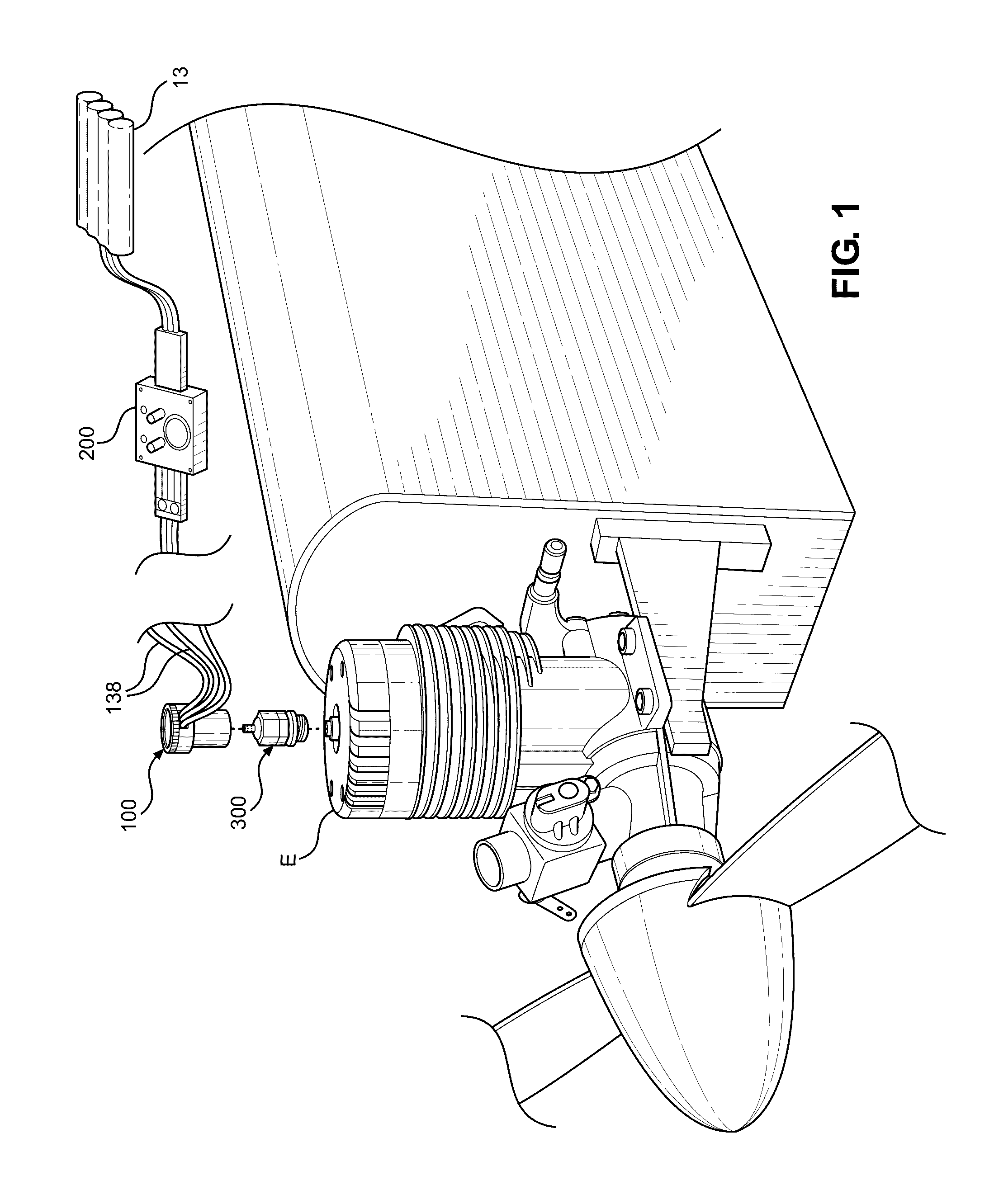
[0037]An autonomous glow driver system for radio controlled (RC) engines is described herein and illustrated in the accompanying figures. Aspects of the system include a connector that securely attaches to the glow plug to maintain good electrical contact with the glow plug and reduce signal noise and using a current and differential amplifiers to determine the temperature of the glow element and the RPMs of the glow engine from a voltage signal obtained via the connector that varies with the temperature induced changes in the resistance of the glow element. Using the data of temperature, non-running RPM, and running RPM to control operation of the glow driver leads to a very reliable approach to automatically activating the glow driver to maintain the combustion chamber temperature of the glow engine at a selected level because RPM is indicative of a rotating engine whereas temperature is not.

[0038]FIG. 1 illustrates on embodiment of a connector 100 for use in connection with a mod...


PUM


Abstract

An autonomous glow driver system for radio controlled (RC) engines. Aspects of the system include a connector that securely attaches to the glow plug to maintain good electrical contact with the glow plug and reduce signal noise and using a current and differential amplifiers to determine the temperature of the glow element and the RPMs of the glow engine from a voltage signal (obtained via the connector) that varies with the temperature as induced changes in the resistance of the glow element occur. Using the data of temperature, non-running RPM, and running RPM to control operation of the glow driver leads to a very reliable approach to automatically activating the glow driver to maintain the combustion chamber temperature of the glow engine at a selected level because RPM is indicative of a rotating engine whereas temperature is not.

Description

CROSS-REFERENCE TO RELATED APPLICATIONS[0001]Not Applicable.BACKGROUND[0002]This invention relates to the field of glow drivers and, in particular, to a connector and controller used for transmitting and controlling the delivery of electrical power from an energy supply to a glow plug when starting and running a model glow engine used in a radio controlled (RC) vehicle.[0003]Small engines, such as those used in remote-controlled model airplanes, cars, boats, etc. are described as a glow engine because they are equipped with a glow plug. The glow plug, which includes a resistive circuit or glow element, is typically threaded into the engine so that the glow element is located in the combustion chamber of the engine. In operation, the glow element is used to facilitate the catalytic reaction between an air / fuel mixture and the glow element, which takes place within the combustion chamber. This reaction produces useful mechanical power used for powering the vehicle. In starting and ope...

Claims


Application Information

Patent Timeline
IPC IPC(8): F02P19/02F02B75/34
CPCF02P19/023F02B75/34F02P19/026F02P19/025F02N19/04F02N2300/306F02N11/0807
Inventor DEMMONS, SHELDON J.
Owner DEMMONS SHELDON J
Why Eureka
Try Eureka