
Predictive building control system and method for optimizing energy use and thermal comfort for a building or network of buildings

a building or building network technology, applied in the field of building control systems, can solve the problem of not providing the degree of granular thermal zone-level comfort control

Active Publication Date: 2016-10-20
GREEN POWER LABS INC
View PDF7 Cites 211 Cited by
  • Summary
  • Abstract
  • Description
  • Claims
  • Application Information

AI Technical Summary

Benefits of technology

The patent describes a method, system, and apparatus for controlling the temperature in a building's thermal zone. The method involves using a processor to receive a desired temperature range for the thermal zone and the expected ambient temperature value for the external surface of the building. A predictive model is then used to determine set points for the building's HVAC system that minimize energy use. These set points are then controlling the HVAC system to maintain the actual temperature value of the thermal zone within the desired range. The invention can help reduce energy usage in buildings and provide better control over their temperature.

Problems solved by technology

Heating and cooling account for most of a building's energy consumption and typically are the most expensive items with respect to building energy costs as electrical power for heating and cooling is often purchased at peak rates.
While addressing important areas of building energy use optimization by using techniques like building energy modeling, control set point optimization, and model predictive control, one problem with existing methods and systems for building HVAC control such as those described in the above examples, is that they do not provide the degree of granular thermal zone-level comfort control, while optimizing overall energy use, that is required for today's buildings and networks of buildings.

Method used


Image

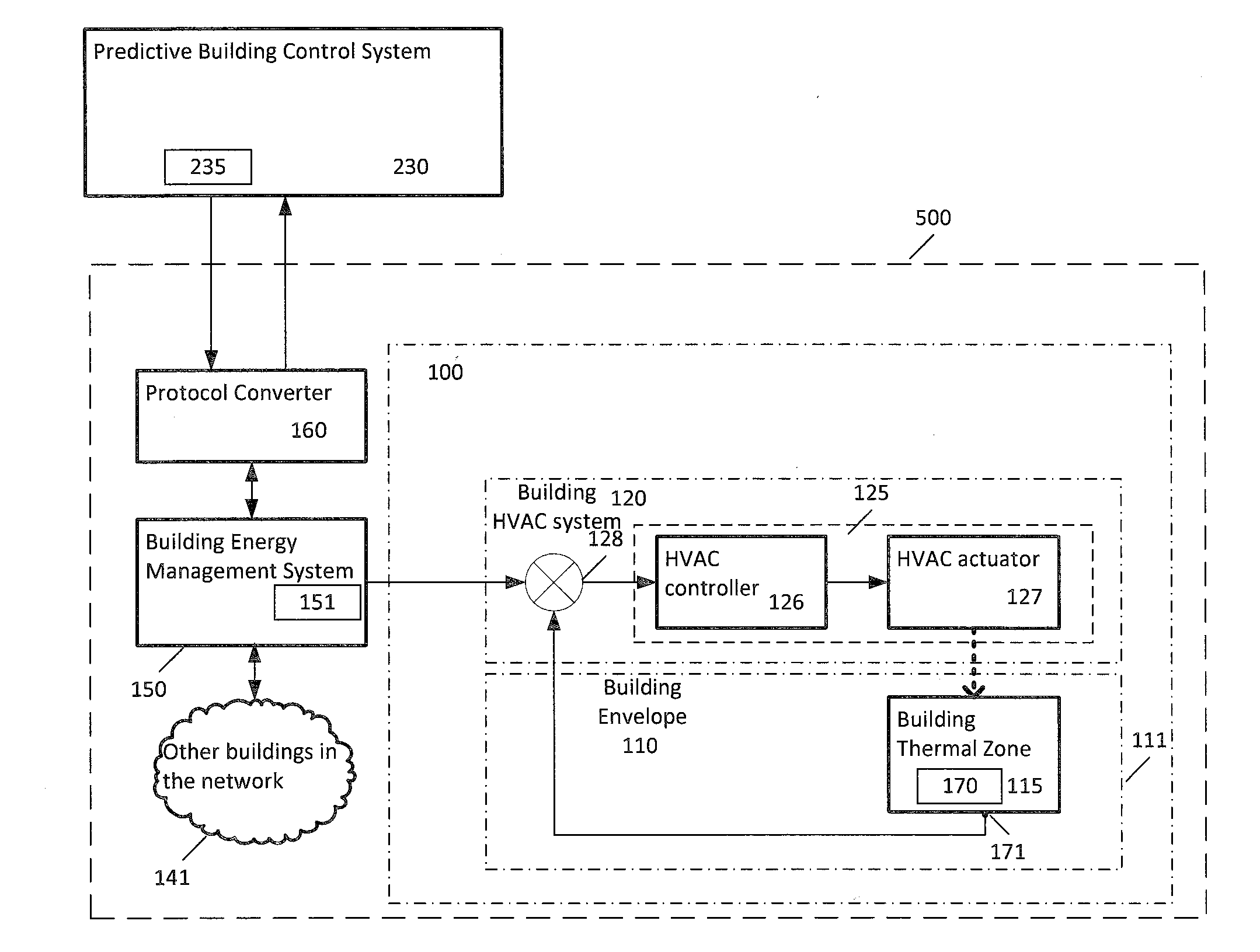
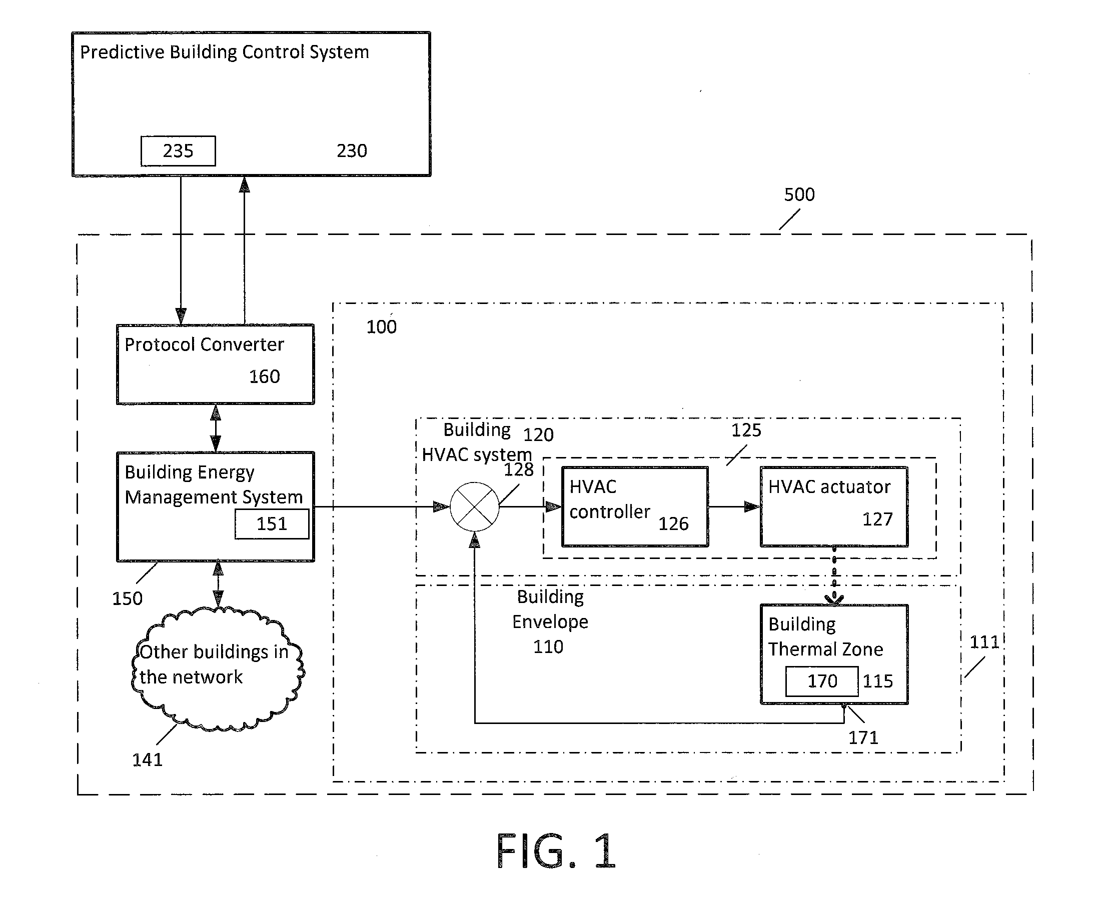
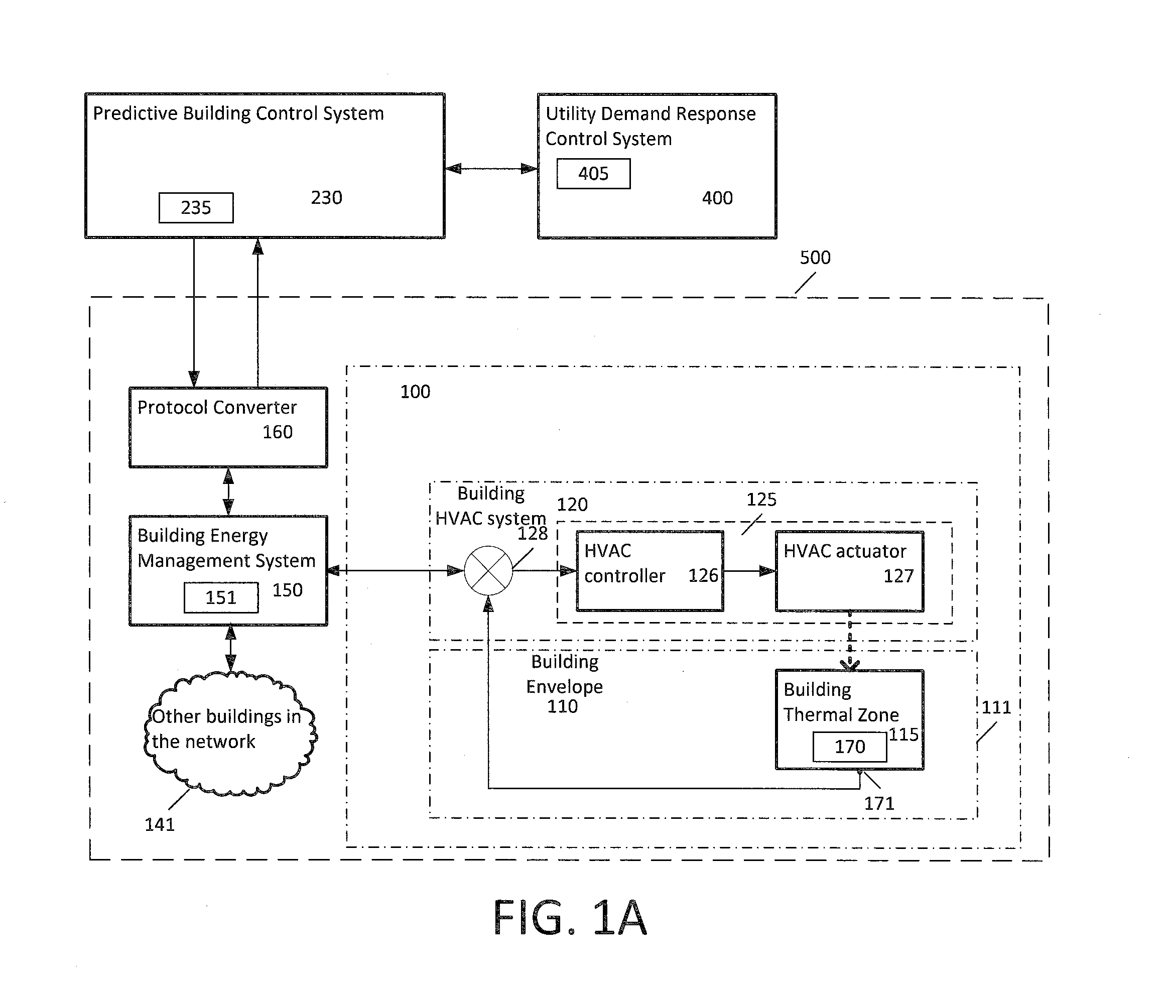
  • Predictive building control system and method for optimizing energy use and thermal comfort for a building or network of buildings
  • Predictive building control system and method for optimizing energy use and thermal comfort for a building or network of buildings
  • Predictive building control system and method for optimizing energy use and thermal comfort for a building or network of buildings

Examples


Embodiment Construction

[0043]In the following description, details are set forth to provide an understanding of the invention. In some instances, certain software, circuits, structures and methods have not been described or shown in detail in order not to obscure the invention. The term “data processing system” or “system” is used herein to refer to any machine for processing data, including the predictive building control systems, building energy management systems, utility demand response control systems, control systems, controllers, and network arrangements described herein. The present invention may be implemented in any computer programming language provided that the operating system of the data processing system provides the facilities that may support the requirements of the present invention. Any limitations presented would be a result of a particular type of operating system or computer programming language and would not be a limitation of the present invention. The present invention may also be...


PUM


Abstract

A method for controlling temperature in a thermal zone within a building, comprising: using a processor, receiving a desired temperature range for the thermal zone; determining a forecast ambient temperature value for an external surface of the building proximate the thermal zone; using a predictive model for the building, determining set points for a heating, ventilating, and air conditioning (“HVAC”) system associated with the thermal zone that minimize energy use by the building; the desired temperature range and the forecast ambient temperature value being inputs to the predictive model; the predictive model being trained using respective historical measured value data for at least one of the inputs; and, controlling the HVAC system with the set points to maintain an actual temperature value of the thermal zone within the desired temperature range for the thermal zone.

Description

FIELD OF THE INVENTION[0001]This invention relates to the field of building control systems, and more specifically, to a method and system for predictive building control for optimizing energy use and thermal comfort for a building or network of buildings.BACKGROUND OF THE INVENTION[0002]Commercial, residential, and industrial buildings are responsible for a significant portion of the world's total energy use. Heating and cooling account for most of a building's energy consumption and typically are the most expensive items with respect to building energy costs as electrical power for heating and cooling is often purchased at peak rates. While the cost of heating and cooling buildings is increasing, the thermal comfort of building occupants remains an important concern as such comfort supports occupants' productivity, health, and is related to optimal operating conditions for buildings whether they be residential, commercial, or industrial.[0003]A network or buildings (or a building ...

Claims


Application Information

Patent Timeline
Patent Type & Authority Applications(United States)
IPC IPC(8): F24F11/00G05B13/04F24F11/76
CPCF24F11/006F24F11/0012F24F11/0034G05B13/048F24F2011/0013F24F2011/0035F24F2011/0075F24F2011/0047F24F2011/0049F24F2011/0058F24F2011/0063F24F2011/0064F24F2011/0046G05B15/02G05B2219/2642F24F2110/10F24F2110/12F24F2120/10F24F2120/12F24F2140/50F24F2140/60F24F2130/20F24F2130/00F24F2130/10F24F11/62F24F11/64F24F11/65F24F11/46G05D23/1917G05D23/1934F24F11/47F24F11/30F24F11/58F24F11/54
Inventor PAVLOVSKI, ALEXANDREQIN, ZHENGANICHKOV, DMITRIYFLETCHER, JAMES
Owner GREEN POWER LABS INC
Learn More