Electric gripper system and control method thereof

Active Publication Date: 2016-10-27
HIWIN TECH
View PDF3 Cites 1 Cited by
  • Summary
  • Abstract
  • Description
  • Claims
  • Application Information

AI Technical Summary

Benefits of technology

The present invention is an electric gripper system with a control method that prevents positional deviation during movement. The control unit receives a relative-position command value and an absolute cumulative position. The control unit generates a target position and a driving program to move the gripper mechanism to the target position. The driving segment reads the driving program and drives the motor to move the gripper mechanism, eliminating positional deviation and improving positioning accuracy. This invention ensures accurate movement of the electric gripper.

Problems solved by technology

However, the existing electric gripper tends to have a minor positional deviation from the targeted site every time it moves.
As a result, the workpiece it holds can leave its intended route and collide with the workpieces on which it is to be assembled.
In the prior art as stated above, while it is possible to improve of the accuracy of each-time displacement of the step motor by feeding back the step motor's current position, there is no means to compensate cumulative deviation that results from individual minor positional deviation over several times of the step motor's movement.

Method used


Image

  • Electric gripper system and control method thereof
  • Electric gripper system and control method thereof
  • Electric gripper system and control method thereof

Examples


Embodiment Construction

[0019]The invention as well as a preferred mode of use, further objectives and advantages thereof will be best understood by reference to the following detailed description of illustrative embodiments when read in conjunction with the accompanying drawings.

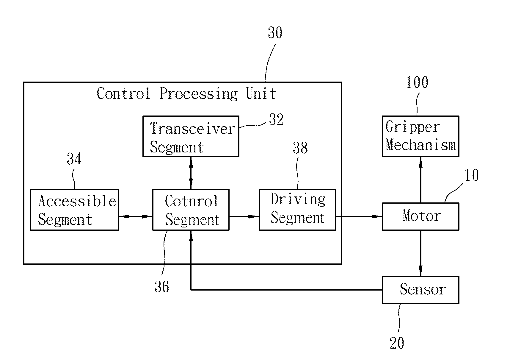
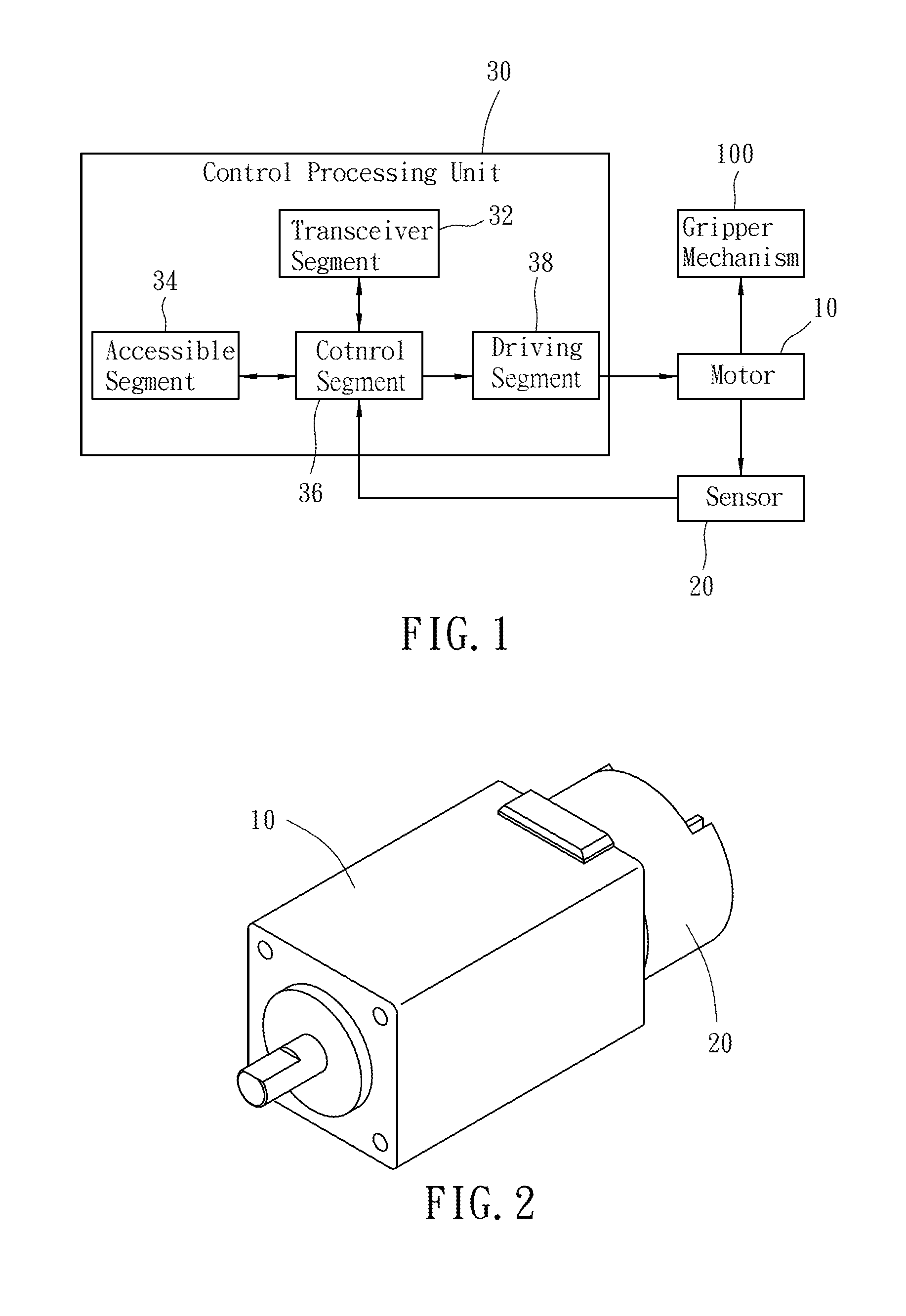
[0020]Referring to FIG. 1 and FIG. 2, an electric gripper system according to one preferred embodiment of the present invention serves to drive a gripper mechanism 100 to perform displacement. The electric gripper system comprises a motor 10, a sensor 20, and a control processing unit 30. The motor 10 serves to drive the gripper mechanism 100 to perform displacement.

[0021]As shown in FIG. 1, the sensor 20 is assembled onto the motor 10. The sensor 20 generates a current position of the gripper mechanism 100 according to the position of the gripper mechanism 100.

[0022]The control processing unit 30 comprises a transceiver segment 32, an accessible segment 34, a control segment 36, and a driving segment 38. The control segment 36 is...


PUM


Abstract

An electric gripper system includes a motor driving a gripper mechanism, a sensor, and a control processing unit. The sensor is assembled onto the motor for generating a current position of the gripper mechanism. The control processing unit has a control segment, a transceiver segment, an accessible segment, and a driving segment. The control segment generates a target position according to a relative-position command value of the transceiver segment and an absolute cumulative position of the accessible segment. The control segment generates a driving datum based on a difference between the current position and the target position, and on a rotation rate of the motor. The driving segment uses the driving datum to drive the motor to move the gripper mechanism. With calculation among the relative-position command value, the absolute cumulative position, and the current position, the motor is prevented from accumulating positional deviation.

Description

BACKGROUND OF THE INVENTION[0001]1. Technical Field[0002]The present invention relates to an electric gripper system and a control method thereof, and is applicable to an electric gripper for improving the gripper mechanism in terms of positioning accuracy.[0003]2. Description of Related Art[0004]Electric grippers have been extensively used in automated industry for gripping workpieces to be assembled. However, the existing electric gripper tends to have a minor positional deviation from the targeted site every time it moves. Such positional deviation can continuously accumulate. Over time, the electric gripper the difference between the actually reached site and the targeted site can become significant. As a result, the workpiece it holds can leave its intended route and collide with the workpieces on which it is to be assembled.[0005]As disclosed in U.S. Pat. No. 7,863,851, the positional deviation generated when an electric gripper moves is offset. This prior-art device has a fir...

Claims


Application Information

Patent Timeline
IPC IPC(8): B25J9/16
CPCB25J9/1612G05B19/29G05B2219/42204G05B2219/42249
Inventor CHEN, WEI-SHAOHUANG, KAI-HSIANGTSENG, I-HSIANG
Owner HIWIN TECH
Why Eureka
Try Eureka