Traveling vehicle system

Pending Publication Date: 2022-02-03
MURATA MASCH LTD
View PDF0 Cites 0 Cited by
  • Summary
  • Abstract
  • Description
  • Claims
  • Application Information

AI Technical Summary

Benefits of technology

This invention provides traveling vehicle systems that can prevent positional deviation of the main body while keeping the structure simple. The guider is integrally connected to the coupler, so it can switch its direction according to the change in the traveling wheel's direction, reducing positional deviation of the main body and avoiding complexity in the vehicle structure. In the example where the first and second guide surfaces are the side surfaces of the first and second tracks, the tracks can function as guide surfaces for the guider, preventing the vehicle's dimensions from increasing and reducing space efficiency. The guider's guide roller can also reduce frictional resistance when coming into contact with the guide surfaces.

Problems solved by technology

However, the traveling vehicle in which the traveling wheel changes directions between during traveling along the first track and during traveling along the second track as in the above causes a problem in that when a mechanism to change the direction of the guide roller in accordance with the direction change of the traveling wheel is separately provided, the configuration of the traveling vehicle becomes complicated.
In addition, an increase in the height dimension of the traveling vehicle by placement of the guide roller causes space efficiency near a ceiling of a building or the like in which the traveling vehicle system is installed to reduce.

Method used


Image

  • Traveling vehicle system
  • Traveling vehicle system
  • Traveling vehicle system

Examples


Embodiment Construction

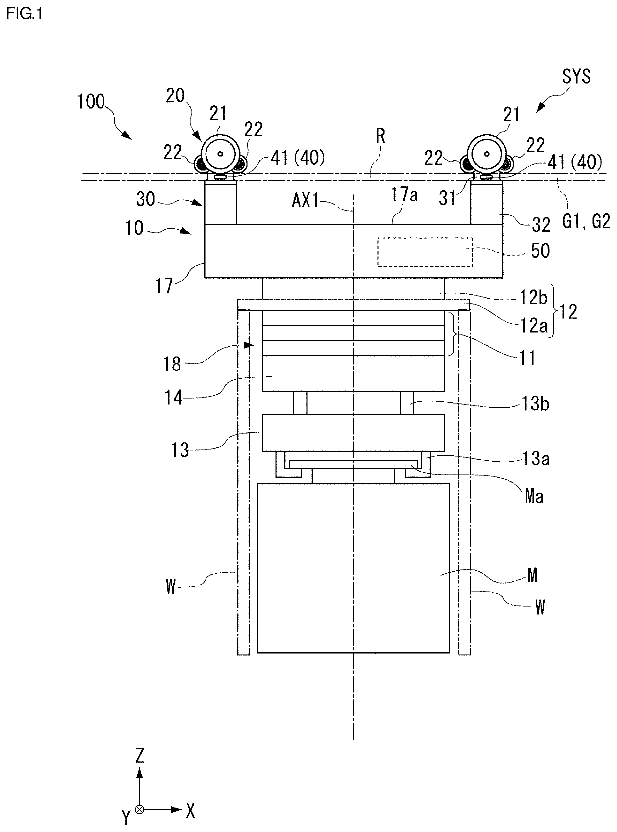
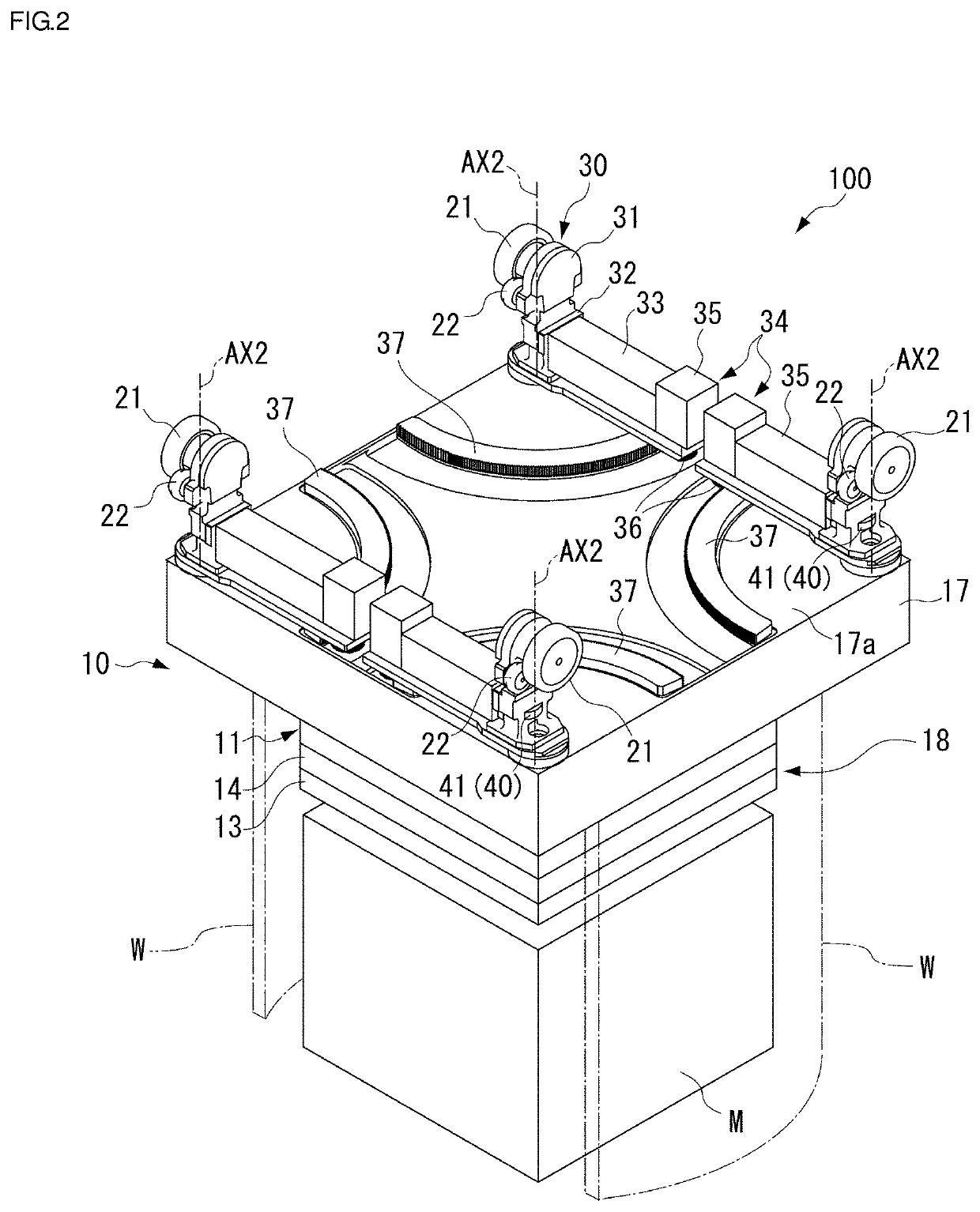
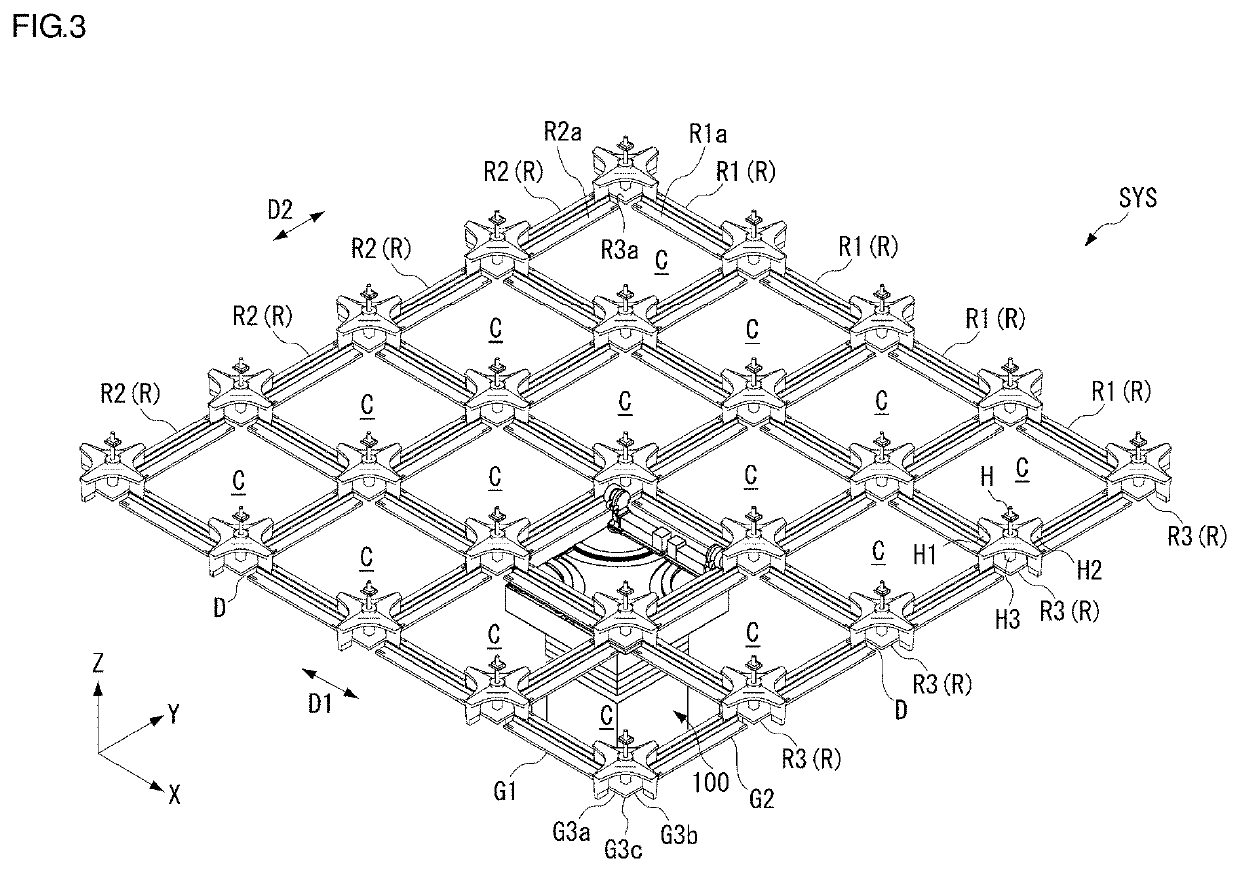
[0024]The following describes preferred embodiments of the present invention with reference to the accompanying drawings. However, the present invention is not limited to the features described herein. To describe the preferred embodiments, the drawings are represented with the scale changed as appropriate, for example, with partially enlarged or emphasized features. In the drawings below, directions in the drawings are described with respect to an XYZ coordinate system. In this XYZ coordinate system, a plane parallel to a horizontal plane is defined as an XY plane. One direction along this XY plane is denoted by an X direction, and a direction orthogonal to the X direction is denoted by a Y direction. A traveling direction of a ceiling traveling vehicle 100 is able to be changed to another direction from the direction illustrated in the drawings below; the ceiling traveling vehicle 100 may travel in a curved direction, for example. A direction perpendicular to the XY plane is denot...


PUM


Abstract

A traveling vehicle system includes a track and a ceiling traveling vehicle. The track includes a first track, a second track, and a connection track. The ceiling traveling vehicle includes a direction changer that turns a coupler, which couples a traveling wheel and a main body to each other and passes through a gap D-between the first track or the second track and the connection track. A guider is provided in the coupler, moves along a first guide surface in a first state in which the traveling wheel rolls on the first track, and moves along a second guide surface in a second state in which the traveling wheel rolls on the second track.

Description

BACKGROUND OF THE INVENTION1. Field of the Invention[0001]The present invention relates to a traveling vehicle system.2. Description of the Related Art[0002]In semiconductor manufacturing factories or the like, a traveling vehicle system conveying articles such as front opening unified pods (FOUPs) housing semiconductor wafers and reticle pods housing reticles by traveling vehicles is used, for example. As this type of traveling vehicle system, a configuration is known to include a track including a first track extending along a first direction, a second track extending along a second direction different from the first direction, and a connection track connecting the first track and the second track to each other, a traveling wheel rolling on the track, a main body located below the track, a coupler coupling the traveling wheel and the main body to each other, and a direction changer integrally rotating the traveling wheel and the coupler (refer to International Publication No. WO20...

Claims


Application Information

Patent Timeline
IPC IPC(8): B61B3/02B61B13/02
CPCB61B3/02B61B13/02H01L21/67733H01L21/67706H01L21/6773H01L21/67715B65G1/0457B66C17/06B66C7/02B65G2201/0297
Inventor OGO, HARUKIISHIKAWA, KAZUHIROITO, YASUHISATORAZAWA, MASAYOSHI
Owner MURATA MASCH LTD
Why Eureka
Try Eureka