

Vehicle brake system
Patent Information
- Authority / Receiving Office
- US · United States
- Current Assignee / Owner
- HONDA MOTOR CO LTD
- Publication Date
- 2016-10-27
Smart Images
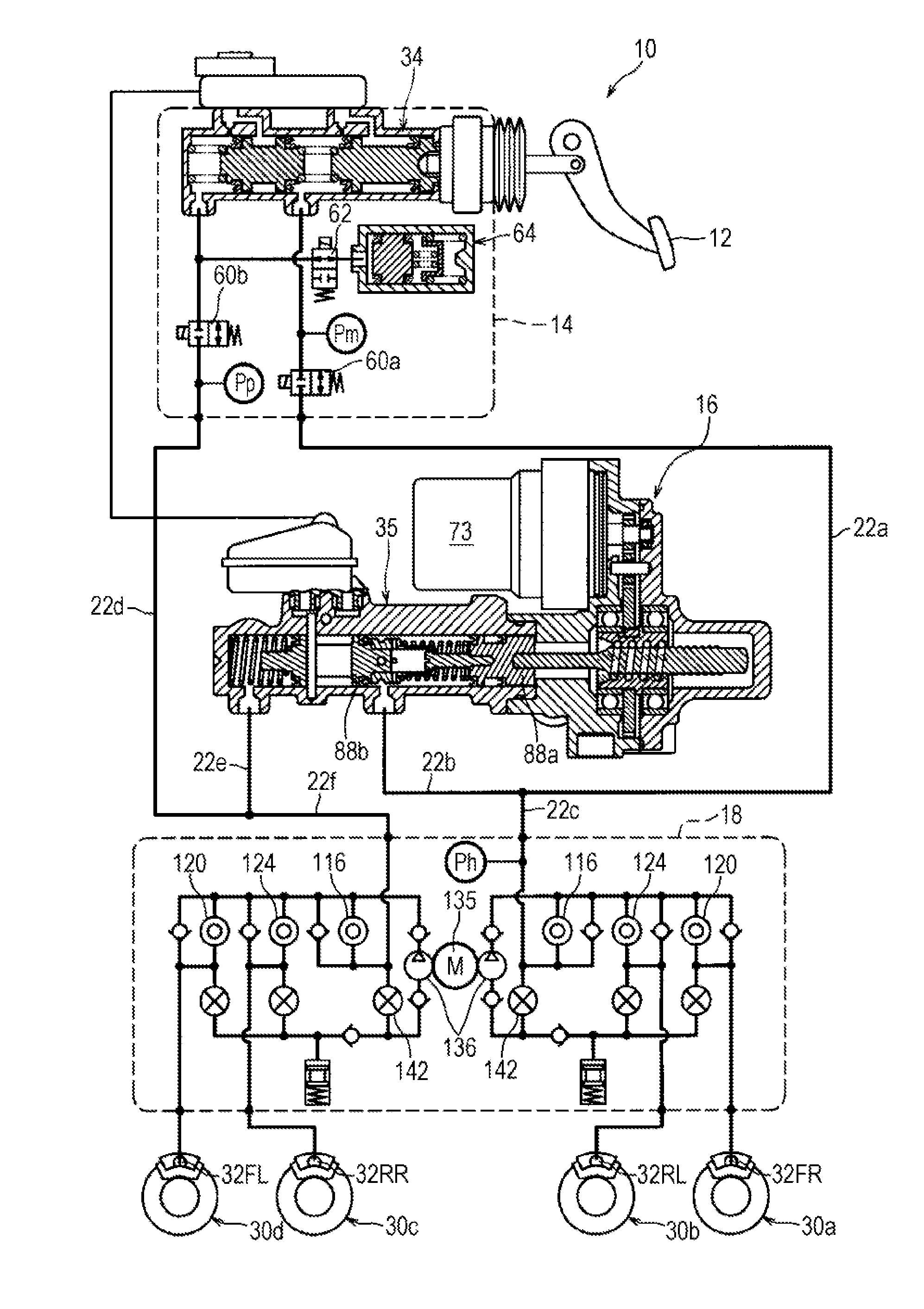
Figure 1 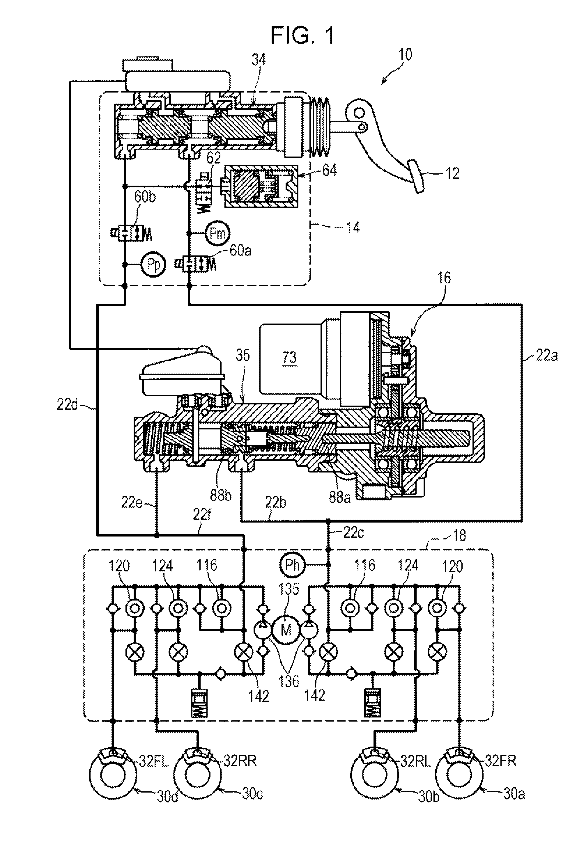
Figure 2 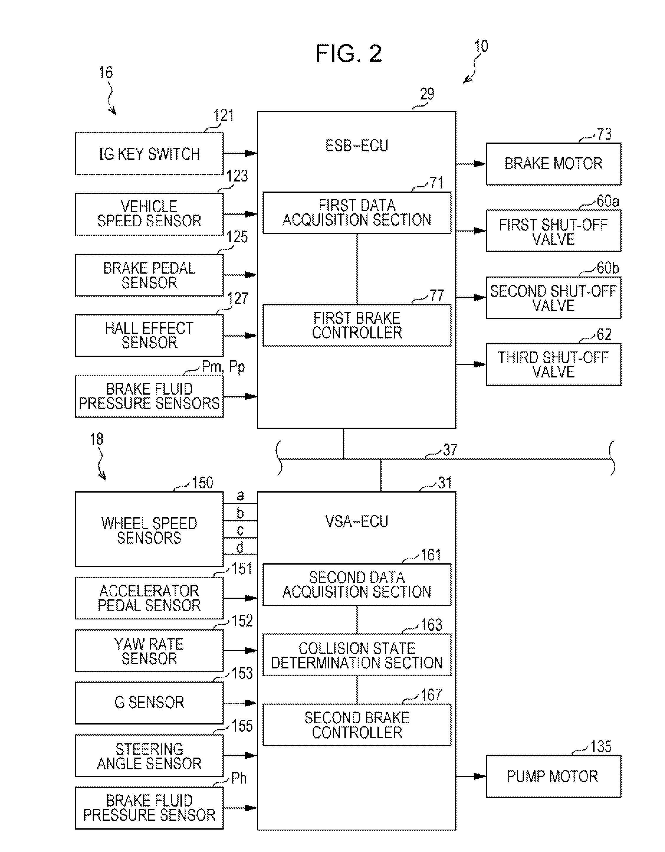
Figure 3
Abstract
Description
CROSS REFERENCES TO RELATED APPLICATIONS
[0001] The present application claims priority under 35 U.S.C. §119 to Japanese Patent Application No. 2015-090271, filed Apr. 27, 2015, entitled “Vehicle Brake System.” The contents of this application are incorporated herein by reference in their entirety.BACKGROUND
[0002] 1. Field
[0003] The present disclosure relates to a vehicle brake system for braking a vehicle.
[0004] 2. Description of the Related Art
[0005] Japanese Unexamined Patent Application Publication No. 2012-001091 describes an example of a vehicle brake system for braking a vehicle. The vehicle brake system according to Japanese Unexamined Patent Application Publication No. 2012-001091 is equipped with a collision sensor for detecting a collision of the vehicle and a vehicle speed sensor for detecting vehicle speed of the vehicle. When a collision of the vehicle is detected by the collision sensor, an automatic braking period, this being a period during which braking force is generate...