Focusing ultrasonic source

a technology of ultrasonic sources and aperture angles, applied in the field of ultrasonic source, can solve the problems of difficult to avoid or reduce the damage to other tissues in the human body in the ultrasonic wave transmission path, the focusing performance of ultrasonic source aperture angles is not desired, and the safety and effectiveness are in conflict, so as to avoid or reduce the damage to other tissues, the effect of high sound intensity and killing tissues

Inactive Publication Date: 2005-08-25
BEIJING YUANDE BIO MEDICAL ENG
View PDF7 Cites 6 Cited by
  • Summary
  • Abstract
  • Description
  • Claims
  • Application Information

AI Technical Summary

Benefits of technology

[0007] The object of the present invention is to provide a focus ultrasonic wave source with a desired focusing performance. The ultrasonic wave source can generate the ultrasonic wave focused to reach a sufficiently high sound intensity and temperature at the focal point so as to kill the tissues while avoiding or reducing the damages to other tissue of the human body in the ultrasonic wave transmission path.
[0010] After tested, it is found that the ultrasonic wave source according to the present invention has a focusing performance substantilly superior to that of the existing ultrasonic wave source with a small aperture angle, and it can cause the focused ultrasonic wave to reach a sufficiently high sound intensity and temperature at the focal point so as to kill the tissues while avoiding or reducing the damages to other tissue of the human body in the ultrasonic wave transmission path, which greatly reduces the pain felt by the patient.

Problems solved by technology

The contradiction between the safety and the effectiveness is the primal problem to be solved in the field of the medical apparatus.
However, in this case, it is difficult to avoid or reduce the damages to other tissue in the human body in the ultrasonic wave transmission path.
According to the present pratice, the focusing performance of the ultrasonic wave sources with such aperture angles is not desired.
Specifically, such wave sources will make the patient feel an evident pain and cause the damage in the transmission path, or they can not reach sufficiently high sound intensity and temperature at the focal point for killing the tissues.
In addition, becase of the increase of the size and cost of the ultrasonic wave source and the difficulty in therapy due to the increase of the aperture angle, it is necessary to solve the above problem by setting the aperture angle of the focusing component of the ultrasonic wave source in a desired angle range.

Method used


Image

  • Focusing ultrasonic source
  • Focusing ultrasonic source
  • Focusing ultrasonic source

Examples


Embodiment Construction

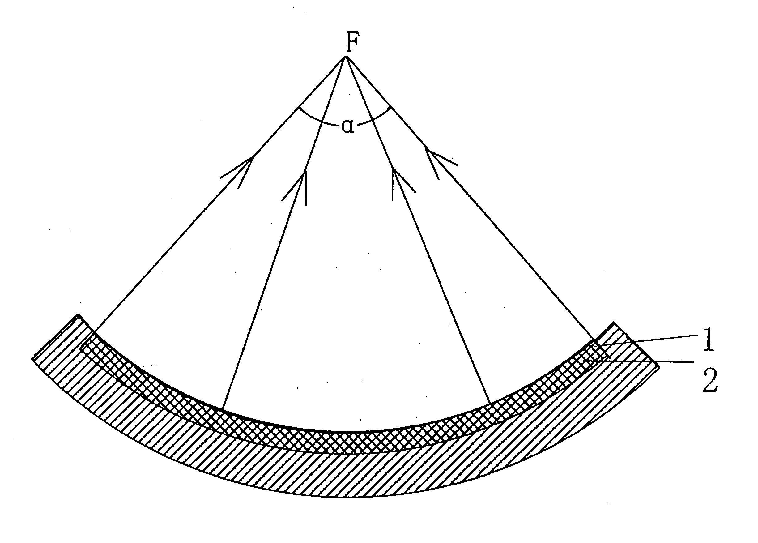
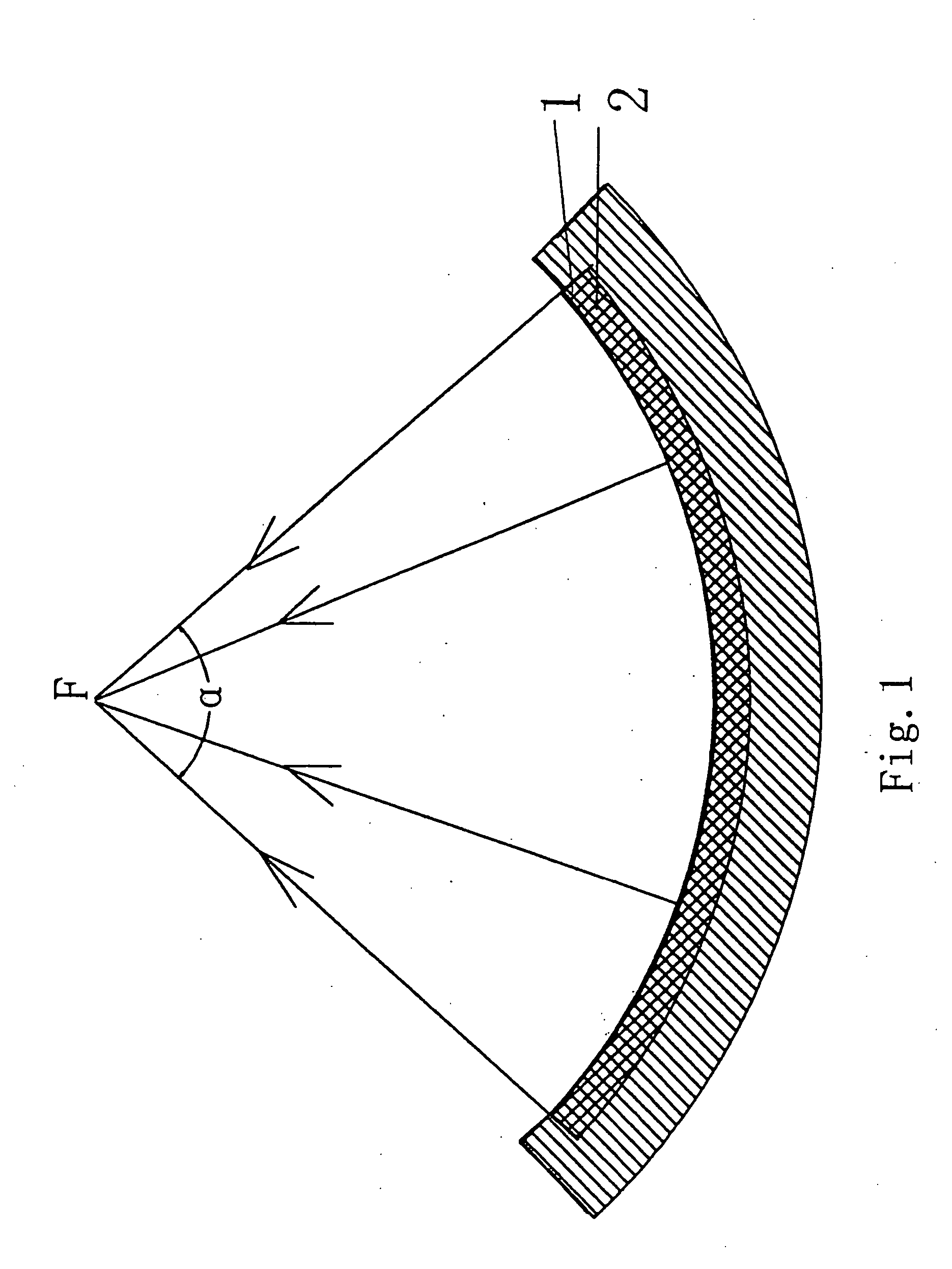
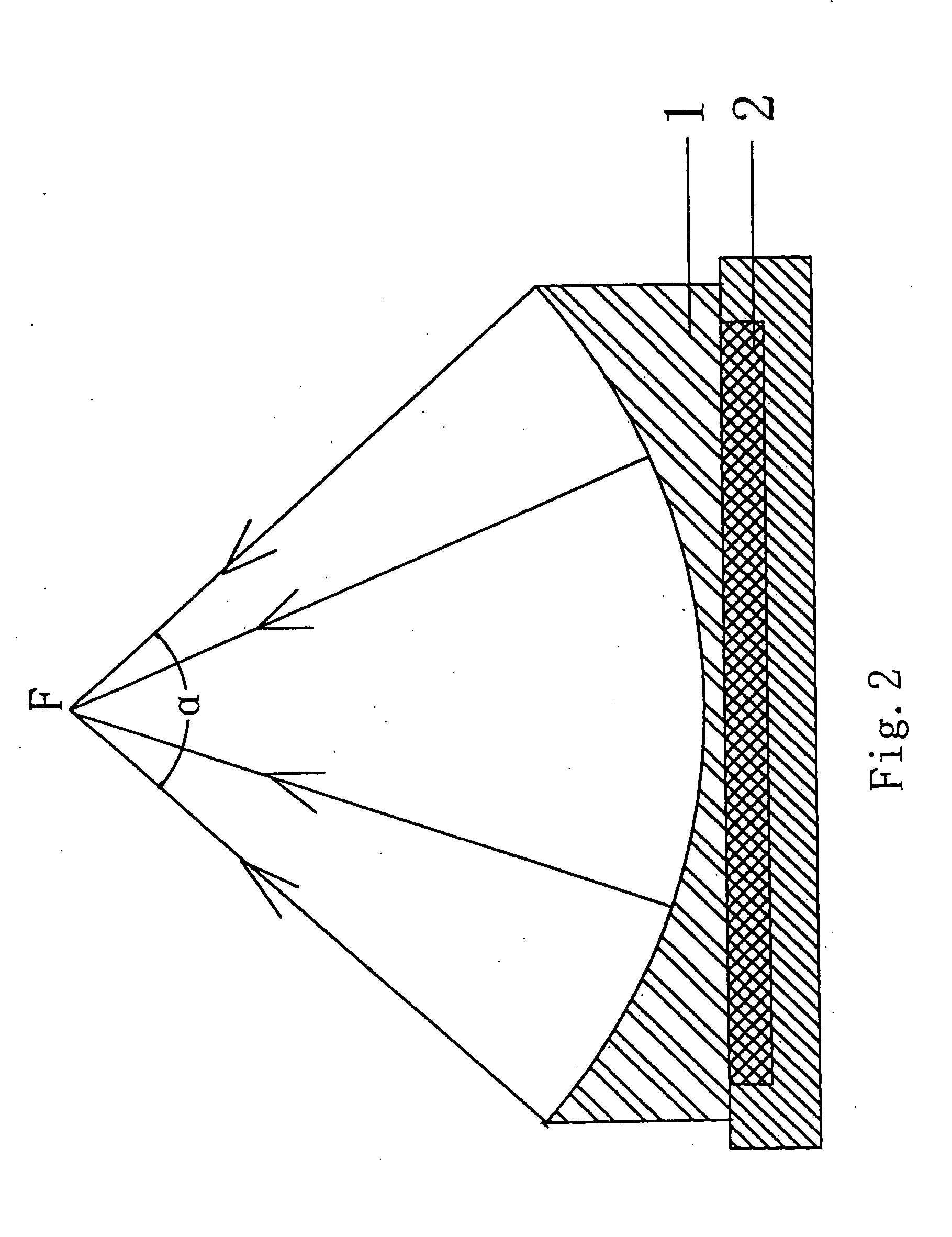
[0014] The drawings schematically show the structural principle views of a focus ultrasonic wave source according to the present invention, which includes an ultrasonic wave emitting component 2 for emiting the ultrasonic wave and a focusing component 1 for focusing the emitted ultrasonic wave, wherein the emitted ultrasonic wave is transmitted to a focal point F in a manner similar to a spherical wave after it is focused by said focusing component 1, and wherein an angle α (i.e. “aperture angle” mentioned above) included between the two lines connecting two end points of the outer peripheral diameter of said focusing component 1 to the focal point respectively is from 50° to 120°.

[0015] Preferably, the angle (aperture angle) a included between the two lines connecting two end points of the outer peripheral diameter of said focusing component to the focal point respectively is from 50° to 60°, such as 56°, or the angle (aperture angle) α is from 60° to 120°, such as 110°.

[0016] Fo...


PUM


Abstract

The present invention provides a focus ultrasonic wave source including an ultrasonic wave emitting component for emiting the ultrasonic wave and a focusing component for focusing the the emited ultrasonic wave, wherein the emitted ultrasonic wave is transmitted to a focal point in a manner similar to a spherical wave after it is focused by said focusing component, and wherein an angle α included between the two lines connecting two end points of the outer peripheral diameter of said focusing component to the focal point respectively is from 50° to 120°. After tested, it is found that the ultrasonic wave source according to the present invention has a focusing performance substantilly superior to that of the existing ultrasonic wave source with a small aperture angle, and it can cause the focused ultrasonic wave to reach a sufficiently high sound intensity and temperature at the focal point so as to kill the body tissues while avoiding or reducing the damages to other tissue of the human body in the ultrasonic wave transmission path, which greatly reduces the pain felt by the patient in clinical applications and achieves a desired effect.

Description

FIELD OF THE INVENTION [0001] The present invention relates to a means for use in a medical apparatus, especially to an ultrasonic wave source for use in a high intensity focus ultrasonic wave (HIFU) therapeutic apparatus. BACKGROUND OF THE INVENTION [0002] At present, the existing extracorporeal HIFU therapeutic apparatus generally includes the following means: a HIFU source and a driving circuit thereof for generating the HIFU; a locating system for searching the object to be treated and moving it to the focal point of the ultrasonic transducer, which includes a medical imaging system (such as the B-Mode Ultrasonoscope), a carrying device for carrying the patient such as a bed surface, and a displacement system for causing the spatial movement of the carrying device with respect to the ultrasonic wave source; a high intensity ultrasonic wave (HIU) transmitter and a processing system for transmission medium. Since the ultrasonic wave adapted to the HIFU must be transmitted into the...

Claims


Application Information

Patent Timeline
Patent Type & Authority Applications(United States)
IPC IPC(8): A61B17/22A61N7/02H04R1/34
CPCA61N7/02A61N7/00
Inventor HE, SHENXUYU, JINSHENGLAN, JIANGWU, XIAODONG
Owner BEIJING YUANDE BIO MEDICAL ENG
Why Eureka
Try Eureka