Apparatus for detecting strip steel edge crack based on correcting CPC system

A technology for detecting strips and steel edges, applied in measuring devices, using electrical devices, using optical devices, etc., can solve problems such as detection, unsuitable edge cracks, etc.

Inactive Publication Date: 2015-09-09
BEIJING SHOUGANG CO LTD
View PDF5 Cites 6 Cited by
  • Summary
  • Abstract
  • Description
  • Claims
  • Application Information

AI Technical Summary

Problems solved by technology

However, the device is not suitable for detecting edge cracks during strip rolling

Method used


Image

  • Apparatus for detecting strip steel edge crack based on correcting CPC system
  • Apparatus for detecting strip steel edge crack based on correcting CPC system
  • Apparatus for detecting strip steel edge crack based on correcting CPC system

Examples


Embodiment 1

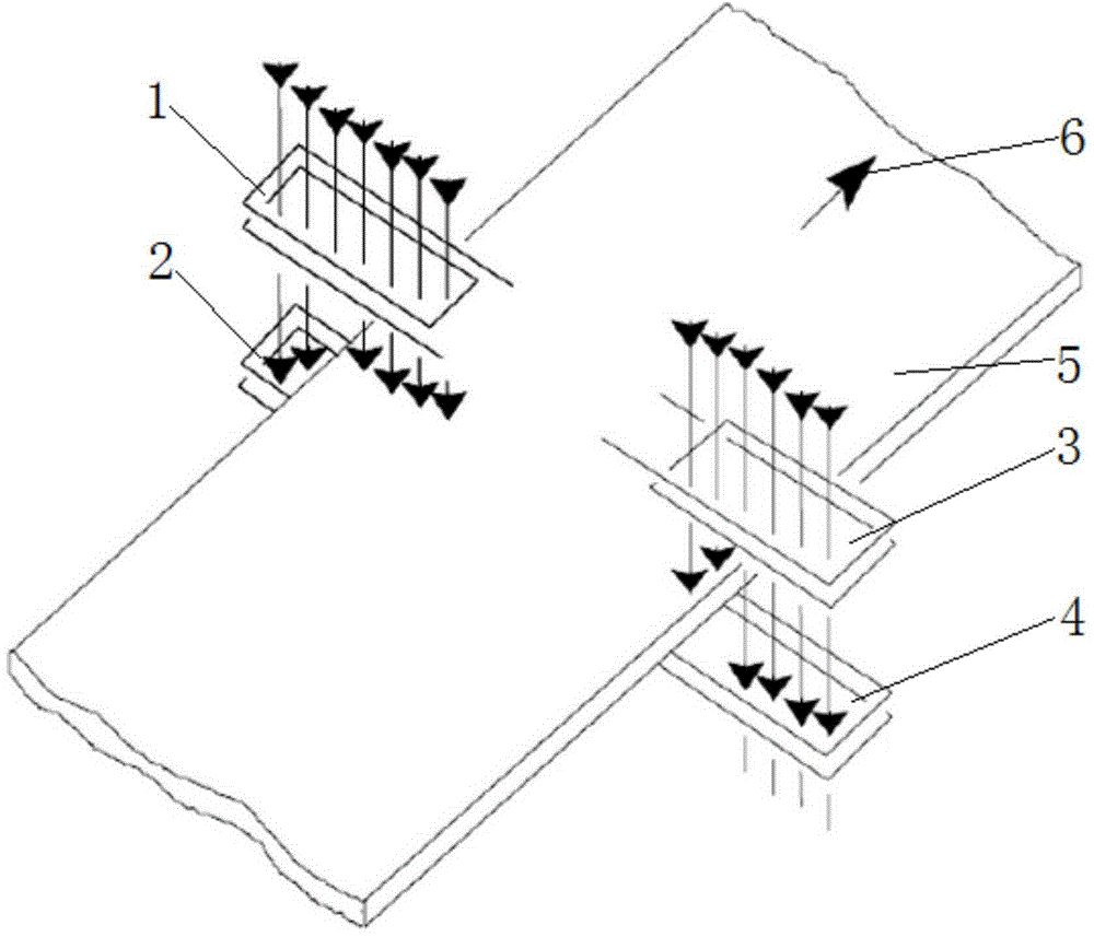
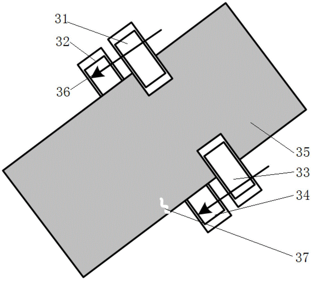
[0033] The first group of sensors and the second group of sensors used in the device for detecting strip edge cracks based on the correction CPC system provided by Embodiment 1 of the present invention are electromagnetic sensors respectively, and the first receiving end 32 is used to receive The electromagnetic signal of the second receiving end 34 is used to receive the electromagnetic signal sent from the second transmitting end 33. When the induced electromotive force detected by the first receiving end 32 and / or the second receiving end 34 suddenly jumps sharply, it is determined that The edge crack occurs at the position where the instantaneous sharp jump is caused on the strip. In this embodiment, on the side where there is a side crack (in this embodiment, the side crack is 37), the side where there is a side crack 37 is the side where the second transmitting end 33 and the second receiving end 34 are located. When the crack 37 moves between the second transmitting end...

Embodiment 2

[0036] The difference from the device for detecting strip edge cracks based on the deviation correction CPC system provided in Embodiment 1 of the present invention is that the first group of sensors used in the device for detecting strip edge cracks based on the deviation correction CPC system provided by Embodiment 2 of the present invention And the second group of sensors are optical sensors, the first receiving end 32 is used to receive the optical signal sent from the first transmitting end 31, and the second receiving end 34 is used to receive the optical signal sent from the second emitting end 33, when the first When the light intensity signal detected by the receiving end 32 and / or the second receiving end 34 has an instantaneous sharp jump, it is determined that the edge crack 37 occurs at the position on the strip 35 where the instant sharp jump occurs. In this embodiment, on the side where there is a side crack (in this embodiment, the side crack is 37), the side wh...

Embodiment 3

[0039] Improvements are made on the basis of the device for detecting strip edge cracks based on the correction CPC system provided in Embodiment 1 or Embodiment 2 of the present invention, and the device for detecting strip edge cracks based on the correction CPC system provided by Embodiment 3 of the present invention also includes an alarm Device, the alarm device is used to alarm the edge crack. Thus, it is convenient for the operator to find the edge crack of the strip in time. In the absence of an alarm device, the staff must stare at the real-time data information displayed on the signal receiving device (not shown in the figure) in real time to find the instantaneous sharp jump of the detection signal, which not only wastes human resources, but is also easy to miss , especially when the instantaneous sharp jump is near the critical value, it is difficult for the staff to judge whether there is an edge crack with the naked eye. However, when selecting the alarm device,...


PUM


Abstract

The invention discloses an apparatus for detecting strip steel edge crack based on a correcting CPC system, and belongs to the technical field of strip steel product defect detection. The apparatus comprises a first emitting end, a first receiving end, a second emitting end, a second receiving end, a signal transmission device and a signal receiving device, wherein the first emitting end and the first receiving end form a first sensor set, and the second emitting end and the second receiving end form a second sensor set. When the signal values that the signal receiving device is received from the first receiving end and the second receiving end changes instantly and greatly during a strip steel rolling process, cracking of the strip steel on the position causing the instant and great change is determined. The apparatus detects edge cracking during a strip steel rolling process, so that workers can timely process detected edge cracking. Damage of equipment due to cracking edge can be minimized or prevented.

Description

technical field [0001] The invention relates to the technical field of strip steel product defect detection, in particular to a device for detecting strip edge cracks based on a deviation correction CPC system. Background technique [0002] On the strip processing line, the deviation of the strip may occur due to different reasons, and the deviation may cause damage to the product or damage to the production equipment. In order to avoid strip deviation, the strip centering control system should be installed at a suitable position on the processing line to ensure that it is always at the center line of the unit during the strip production process. Among them, the strip deviation may be caused by the product itself (such as: camber or wave shape, misalignment or skew of the strip weld), or it may be the cause of the unit equipment, such as the inclination of the support or pressure roller Or only act on one side of the strip, uneven heating and cooling, etc. The functional s...

Claims


Application Information

Patent Timeline
Patent Type & Authority Applications(China)
IPC IPC(8): G01B11/00G01B7/00
Inventor 张立强苗贺武张叶成闫忠旭余威陈凌峰石建锐于海彬
Owner BEIJING SHOUGANG CO LTD
Why Eureka
Try Eureka