Motion Activated Ball Dropping Tool
- Summary
- Abstract
- Description
- Claims
- Application Information
AI Technical Summary
Benefits of technology
Problems solved by technology
Method used
Image

Examples
Embodiment Construction
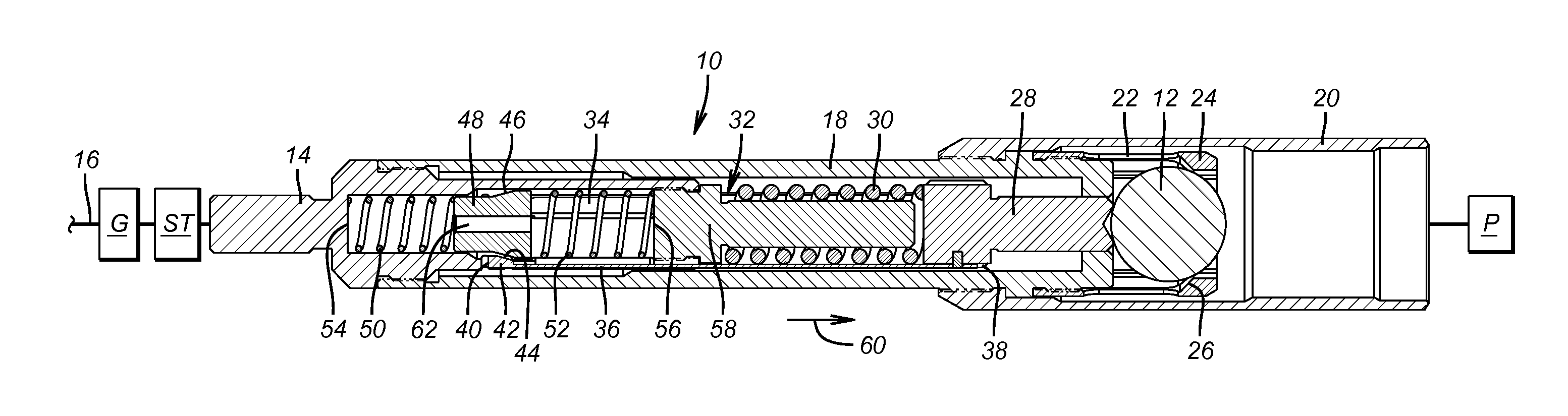
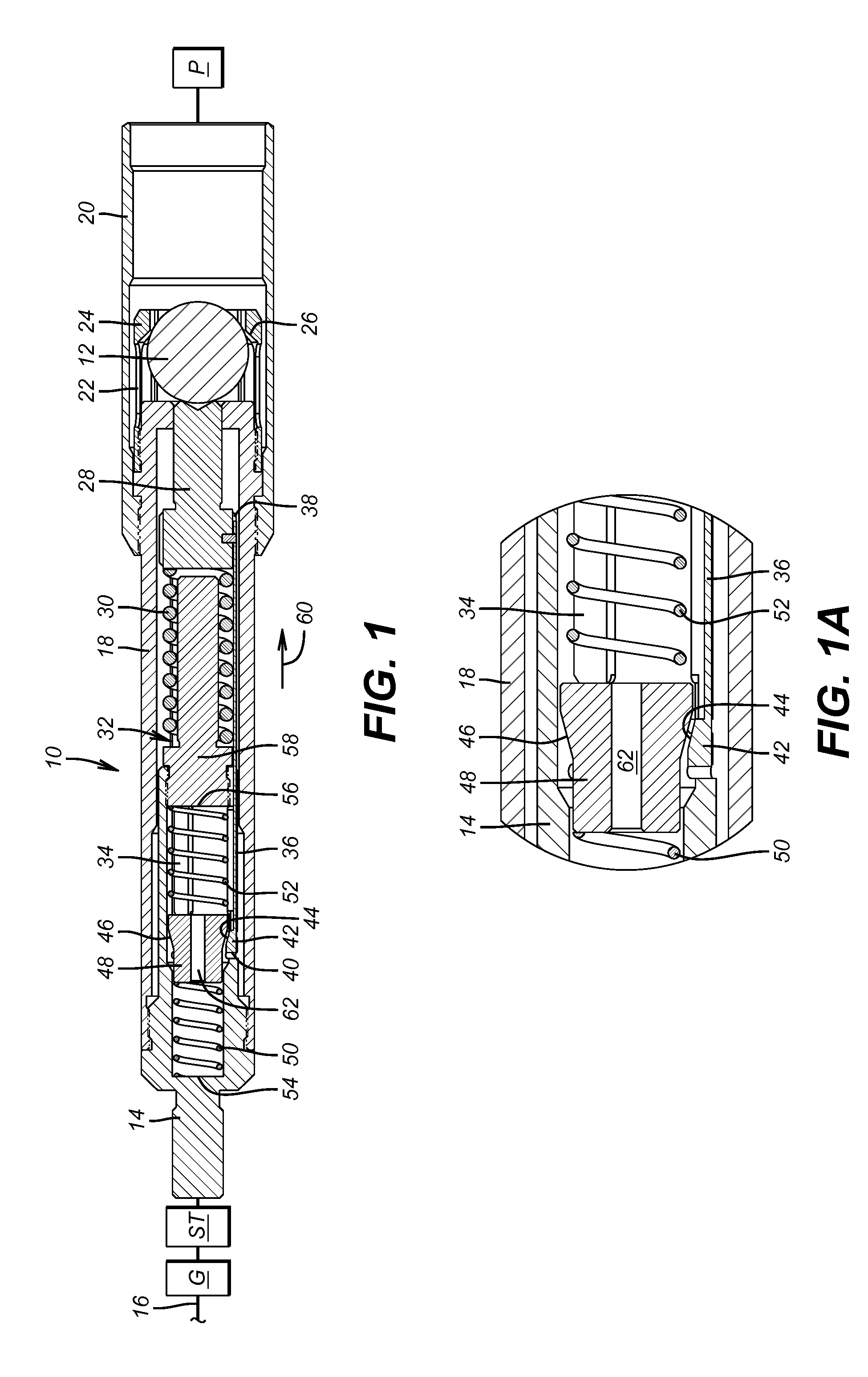
[0023]Referring to the FIGS. 1 and 1a, the tool 10 is part of a bottom hole assembly (BHA) that is not shown. In a fracturing context where the object is to release a ball 12 after setting off a perforating gun that is not shown, the outer housing comprises a top sub 14 below a perforating gun G and a frack plug setting tool ST with the BHA supported on a wireline 16. The frack plug P is initially supported below the tool 10. The top sub 14 is connected to the body 18 which is in turn connected to the lower sub 20. An array of collet fingers 22 having enlarged heads 24 create a retaining seat 26 for the ball 12 during running in. Piston 28 is run in under pressure from compressed spring 30 which is the power spring that will ultimately move the piston 28 to push the ball 12 past seat 26 as the fingers 22 with heads 24 flex radially outwardly.
[0024]What holds the power spring 30 in the compressed state for running in is link assembly 32 which comprises a number of elongated equally s...
PUM
 Abstract
Description
Claims
Application Information