Conveyor Belt Monitoring System and Method

a technology of conveyor belts and monitoring systems, applied in the field of conveyor belt monitoring, can solve the problems of false or missed alarms, limited measurement techniques, and small temperature anomalies, especially those smaller than the spot siz

Active Publication Date: 2016-10-27
THERMOTEKNIX SYSTEMS LTD
View PDF0 Cites 11 Cited by
  • Summary
  • Abstract
  • Description
  • Claims
  • Application Information

AI Technical Summary

Benefits of technology

[0003]According to a first aspect of the invention there is provided a conveyor belt temperature anomaly detection system, comprising: an infrared line scanner having one or more infrared detectors and arranged to scan the surface of a conveyor belt in a direction perpendicular to the direction...

Problems solved by technology

Such measurement techniques are of limited value as they only offer crude indications of temperature within the area upon which the spot is focussed.
If the spot size is too large then small temperature anomalies, particu...

Method used


Image

  • Conveyor Belt Monitoring System and Method
  • Conveyor Belt Monitoring System and Method
  • Conveyor Belt Monitoring System and Method

Examples


Embodiment Construction

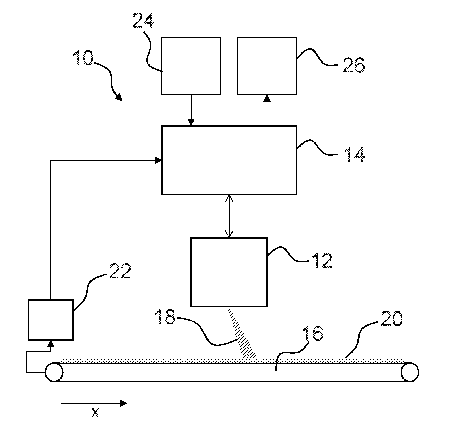
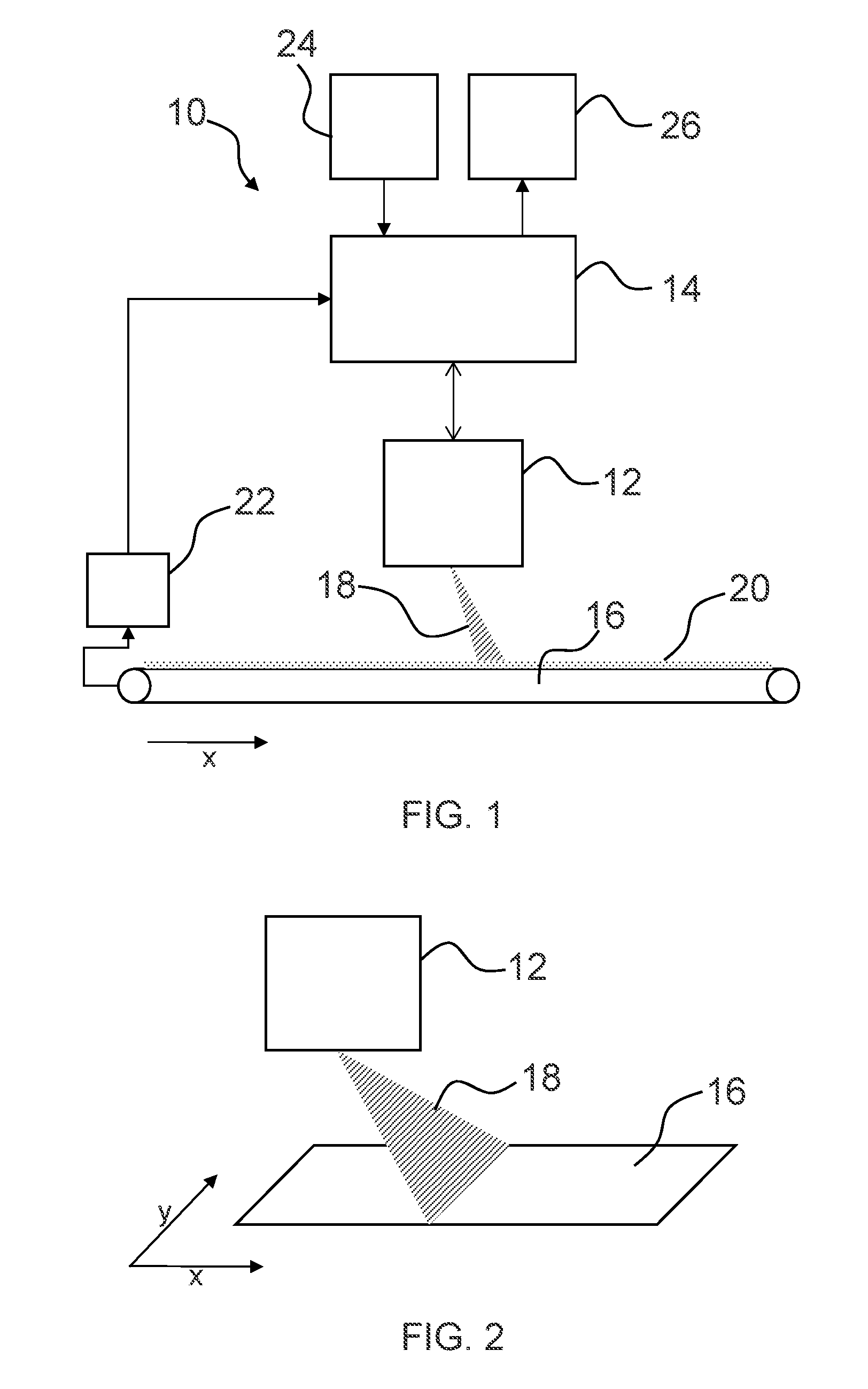
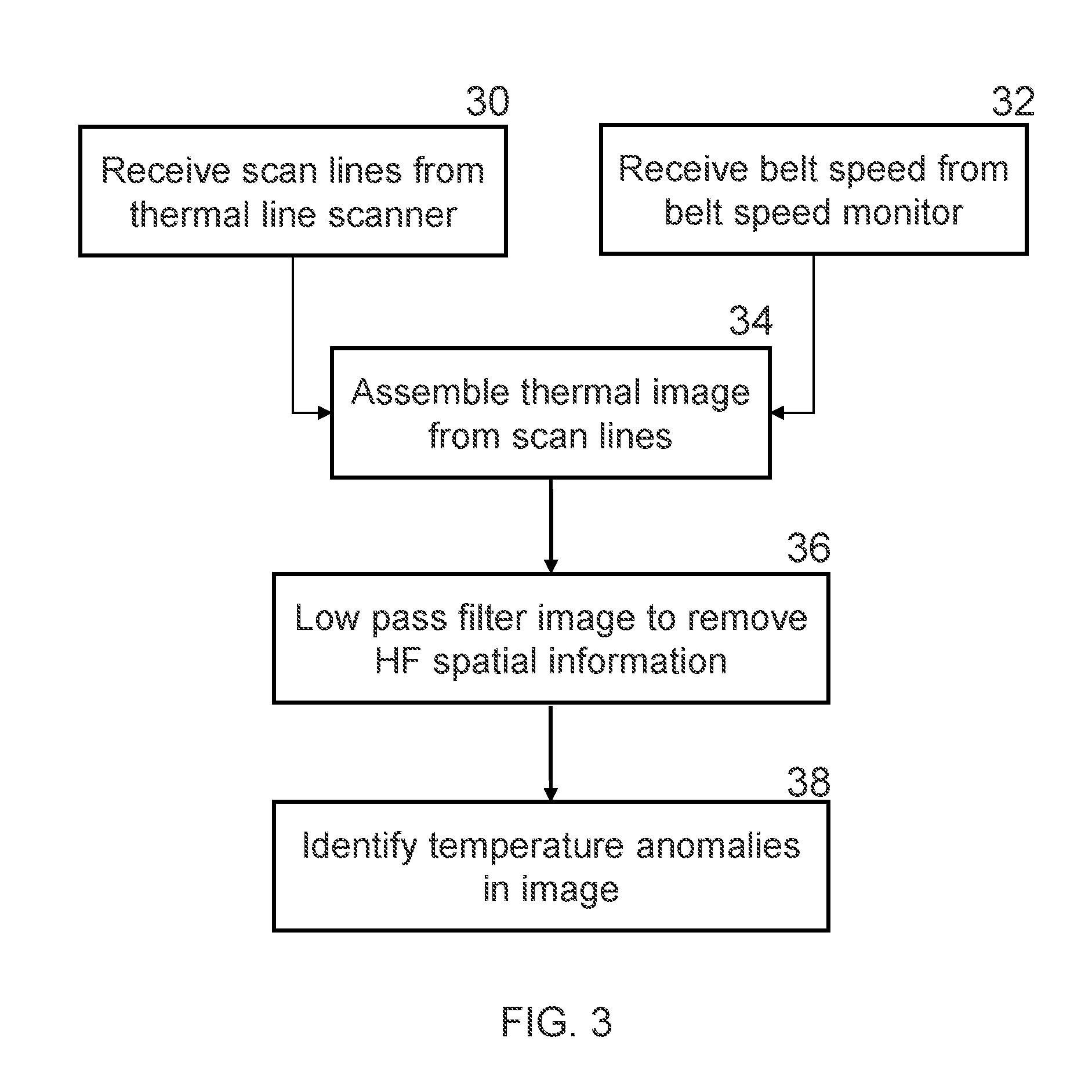
[0016]Embodiments of the present invention overcome the drawbacks associated with conventional spot pyrometer measuring techniques by utilizing an infrared line scanner to repeatedly scan the entire width of a conveyor belt as material travels along its surface. Data received from successive line scans can be assembled to form a thermal image of the belt and material situated thereon. Temperature anomalies present in the thermal image can then be identified and presented to a user and an appropriate course of action taken.

[0017]Embodiments of the present invention are described below primarily with reference to the monitoring of cement clinker passing over a conveyor belt, typically to and from process kilns. In cement processing plants, it is desirable to monitor for localised hot spots present in the clinker. It will, however, be appreciated that in other applications, it may be desirable to measure anomalous areas of low temperature, i.e. cold spots in any material travelling ove...


PUM


Abstract

A conveyor belt temperature anomaly detection system, comprising: an infrared line scanner having one or more infrared detectors and arranged to scan the surface of a conveyor belt in a direction perpendicular to the direction of travel of the conveyor belt and to generate thermal image data in dependence on infrared radiation detected by the infrared detector; and a processing unit configured to process the thermal image data to identify temperature anomalies in the material travelling on the surface of the conveyor belt.

Description

FIELD OF THE INVENTION[0001]This invention relates to conveyor belt monitoring and, in particular, a system and method for detecting temperature anomalies in materials passing over conveyor belts.BACKGROUND TO THE INVENTION[0002]There is a requirement in many industries to monitor the temperature of materials moving along conveyor belts. Conventionally, such monitoring is performed using a single spot or point pyrometer directed towards the belt. Such measurement techniques are of limited value as they only offer crude indications of temperature within the area upon which the spot is focussed. If the spot size is too large then small temperature anomalies, particularly those smaller than the spot size, may be missed. Alarms associated with point pyrometers are limited to an instantaneous local high / low threshold alert in the area of their spot which often lead to false or missed alarms.SUMMARY OF THE INVENTION[0003]According to a first aspect of the invention there is provided a con...

Claims


Application Information

Patent Timeline
IPC IPC(8): G06T7/00G01J5/10G06T7/20G06K9/62H04N5/33G06T7/60
CPCG06T7/0004H04N5/33G06T7/60G06T7/2033G01J2005/0077G01J5/10G06T2207/30164G06T2207/20024G06T2207/10048G06K9/6267B65G43/02G01J2005/0029G01J5/026G01J5/0022G01J5/0066G01J5/07H04N25/701B65G43/00G06T5/009G06T7/0002B65G2203/045G06F18/24
Inventor SALISBURY, RICHARDMITCHELL, ANDREW
Owner THERMOTEKNIX SYSTEMS LTD
Why Eureka
Try Eureka