Unlock instant, AI-driven research and patent intelligence for your innovation.

Low Pressure Dimethyl Ether Synthesis Catalyst

a dimethyl ether and low-pressure technology, applied in the field of catalysis, can solve the problems of reducing the mechanical integrity of the catalyst, reducing the size of the overall reactor, and reducing the bulk density of the final catalyst, so as to reduce the overall reactor size and reduce the capital expenditur

Inactive Publication Date: 2016-11-03
COOL PLANET ENERGY SYST
View PDF3 Cites 4 Cited by
  • Summary
  • Abstract
  • Description
  • Claims
  • Application Information

AI Technical Summary

Benefits of technology

The patent describes a new catalyst that can be used in chemical reactions. This catalyst has a higher density than existing catalysts, which means it can be more effective in a smaller reactor. This results in savings on equipment costs.

Problems solved by technology

These zeolites are expensive.
Addition of dehydrating agent such as zeolites to the catalyst, while needed, reduces the mechanical integrity of the catalyst.
It also reduces the pellet density and compact bulk density of the final catalyst.
A catalyst with lower compact bulk density and lower pellet density might need a physically larger reactor to convert the synthesis gas to DME, thus increasing the overall capital expenditure in a commercial plant.
The capital costs to achieve production on largest scale even with these “low” pressures can be considerable.
The use of dehydration components along with the methanol synthesis catalyst in current DME catalysts increases the overall cost of the catalyst and the reactor to produce DME from synthesis gas.

Method used


Image

  • Low Pressure Dimethyl Ether Synthesis Catalyst
  • Low Pressure Dimethyl Ether Synthesis Catalyst
  • Low Pressure Dimethyl Ether Synthesis Catalyst

Examples


example 1

[0056]The two components of the dimethyl ether synthesis catalyst were made as follows:

[0057]The CuO / ZnO / Al2O3 methanol synthesis catalyst was prepared by a conventional co-precipitation method. HZSM-5 zeolite acid function was prepared by calcining a commercial NH4- ZSM-5 zeolite. ZSM-5 powder was blenderized and calcined at 550° C. in a static air furnace for 8 hours. The bi-functional DME catalyst was prepared by physically mixing the dry metallic function and the acid function powders at desired ratios and mechanically pelletizing them using a suitable lubricant (2% graphite).

[0058]The methanol synthesis catalyst has dopants such as Mn and Cs which are not typical of a commercial methanol synthesis catalyst and the resultant DME catalyst as well. In one embodiment, the catalyst is prepared by metal nitrates co-precipitation at a metal ratio of Cu / Zn / Mn / Cs / Al at 60 / 30 / 5.0 / 0.25 / 4.4. The following nitrate precursors were weighed and placed in 1.5 L metal container.

Cu(NO3)2×2.5H2O-1...

example 2

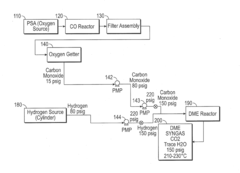
[0067]30 grams of catalyst prepared according to the procedure described above, was used in a laboratory DME reactor. The catalyst was reduced using a flow of hydrogen and nitrogen. The ratio of hydrogen to nitrogen used was 1:9 for catalyst reduction. The catalyst reduction was carried at 230° C. initially and at 270° C. for the last one hour. The effluent of the DME reactor was monitored by using a residual gas analyzer (RGA). FIG. 3 shows the reduction profile of the catalyst as recorded by the residual gas analyzer.

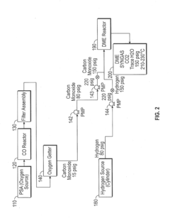
[0068]For measuring the activity of the catalyst, synthesis gas was obtained as follows: While hydrogen was introduced and compressed from the tank to the reactor, CO was generated by reacting a bed of activated carbon at 910° C. using oxygen separated from air and then compressed into the reactor. The effluent from the CO generator at 910° C. also indicates the presence of equilibrium amounts of CO2 and CH4. The gas composition at the entrance of the DME reactor indi...


PUM

PropertyMeasurementUnit
Temperatureaaaaaaaaaa

Abstract

A catalyst and process for synthesis of dimethyl ether from synthesis gas are disclosed. The catalyst and process allow dimethyl ether synthesis at low pressures (below 20 bars) at a conversion rate close to the expected equilibrium rate. The catalyst is a combination of a methanol synthesis catalyst with metal components comprising Cu, Zn, Al, Mn and Cs and a methanol dehydration catalyst, wherein the dehydration catalyst is a dehydration agent which allows optimum production of dimethyl ether.

Description

REFERENCE TO RELATED APPLICATIONS[0001]The application claims the benefit of priority under 35 U.S.C. §119(e) to U.S. Provisional Application Ser. No. 61 / 916,389 filed Dec. 16, 2013, the contents of which is incorporated herein by reference in its entirety.[0002]This application is related to U.S. Ser. No. 13 / 567,991, filed Aug. 6, 2012, and entitled “Low Pressure Dimethyl Ether Synthesis Catalyst”, which claims priority to U.S. Provisional Patent Application No. 61 / 530,813, filed on Sep. 2, 2011, the contents of which is incorporated herein by reference in their entirety.TECHNICAL FIELD[0003]The present invention relates generally to catalysis, and more particularly to a dimethyl ether synthesis catalyst that operates efficiently at low pressures.DESCRIPTION OF THE RELATED ART[0004]Dimethyl ether is a versatile compound capable of being used as a combustion fuel, a cooking fuel, an additive to liquefied propane gas, and an intermediate for the production of other chemical compounds...

Claims


Application Information

Patent Timeline
IPC IPC(8): B01J29/40B01J21/04B01J23/80B01J23/889C07C41/09C07C29/153
CPCB01J29/40C07C41/09B01J21/04B01J23/80B01J23/8892C07C29/153C07C41/01C07C43/043
Inventor MALYALA, RAJASHEKHARAMTRAXLER, VERN S.JARAND, MARK L.THOMPSON, TIMOTHY ALANCHEIKY, MICHAEL C.
Owner COOL PLANET ENERGY SYST