Autonomous safety and recovery system for unmanned aerial vehicles

a technology of unmanned aerial vehicles and recovery systems, which is applied in the field of safe recovery of falling unmanned aerial vehicles, can solve the problems of one or more elements of the aerial vehicle failing, the cost of aerial vehicles themselves can be quite high, and the camera equipment placed on the vehicle can also be very expensive, so as to reduce the input needed and slow down the fall

Inactive Publication Date: 2016-11-03
SKYFALLX LLC
View PDF3 Cites 84 Cited by
  • Summary
  • Abstract
  • Description
  • Claims
  • Application Information

AI Technical Summary

Benefits of technology

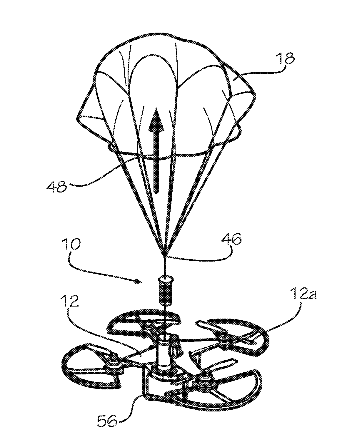
[0014]One objective of the present disclosure is to slow the fall of an aerial vehicle in freefall during an in-flight emergency.
[0015]Another objective of the present disclosure is to provide an autonomous safety system that helps reduce the input needed from an operator to actuate the system.

Problems solved by technology

The aerial vehicles themselves can be quite costly, and in photography applications, the camera equipment placed on the vehicles can also be very expensive.
During flight there is the potential that one or more elements of the aerial vehicles can fail, including but not limited to the motors, batteries, propellers or ESC (electronic speed controllers).
The result of such an equipment failure can result in immediate flight loss, which sends the aerial vehicle into a free fall towards the ground or another object (e.g., a tree, building, person etc.).
Impact with the ground or another object can cause significant and undesirable damage to the vehicle itself or to expensive equipment such as one or more high definition cameras mounted on the vehicle.
Such parachute systems are considerably expensive, in some cases being more expensive than the vehicle they are meant to protect.
Additionally, the system is entirely controlled by the operator, and as such, susceptible to human error.
If the operator becomes distracted and the vehicle experiences flight loss, the operator may not realize the emergency state of the vehicle until after the vehicle has already hit the ground or another object and has potentially been damaged.
Additionally, because many remotely activated systems are based on radio frequency, if the vehicle is flown out of the radio transmitter's range, such systems will not activate even if the operator is aware of the failure and tries to actuate the parachute.

Method used


Image

  • Autonomous safety and recovery system for unmanned aerial vehicles
  • Autonomous safety and recovery system for unmanned aerial vehicles
  • Autonomous safety and recovery system for unmanned aerial vehicles

Examples


Embodiment Construction

[0033]While the making and using of various embodiments of the present invention are discussed in detail below, it should be appreciated that the present invention provides many applicable inventive concepts that are embodied in a wide variety of specific contexts. The specific embodiments discussed herein are merely illustrative of specific ways to make and use the invention and do not delimit the scope of the invention. Those of ordinary skill in the art will recognize numerous equivalents to the specific apparatus and methods described herein. Such equivalents are considered to be within the scope of this invention and are covered by the claims.

[0034]In the drawings, not all reference numbers are included in each drawing, for the sake of clarity. In addition, positional terms such as “upper,”“lower,”“side,”“top,”“bottom,” etc. refer to the apparatus when in the orientation shown in the drawing, or as otherwise described. A person of skill in the art will recognize that the appara...


PUM


Abstract

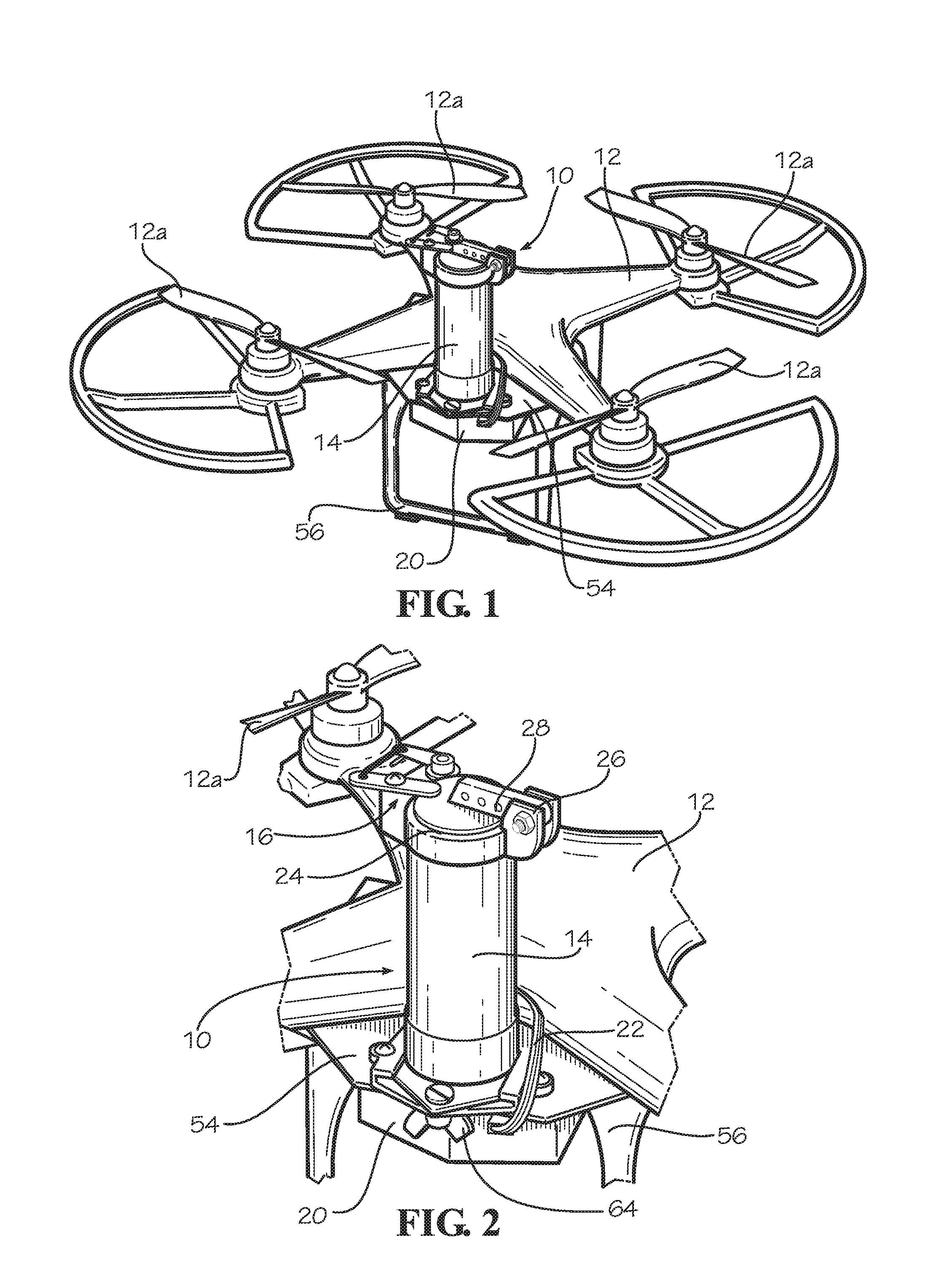
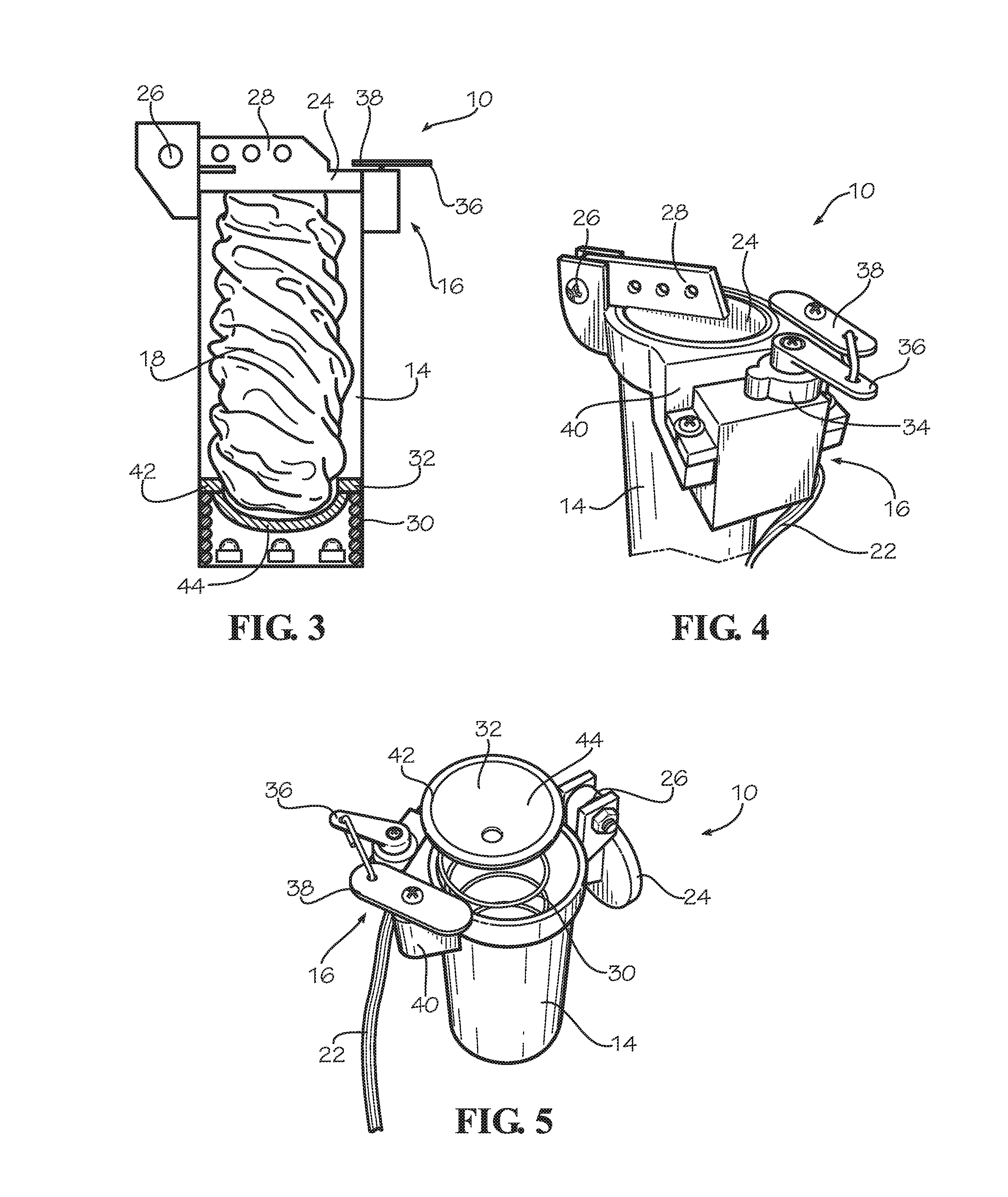
A safety and recovery system for an unmanned aerial vehicle including a parachute holder mountable to the aerial vehicle. A parachute is disposed in the parachute holder. An actuator is engaged with the parachute holder. A flight sensor is in communication with the actuator, the flight sensor programmed to detect one or more predetermined emergency flight conditions, and transmit an emergency signal when the flight sensor detects one of the predetermined emergency flight conditions. The actuator deploys the parachute from the parachute holder when the actuator receives the emergency signal from the flight sensor. Autonomous deployment of the parachute can help minimize damage to the aerial vehicle, equipment on the aerial vehicle, or objects or persons beneath the aerial vehicle, in the event of an emergency.

Description

CROSS-REFERENCES TO RELATED APPLICATIONS[0001]This application claims priority to U.S. Patent Application Ser. No. 62 / 153,942 filed Apr. 28, 2015 entitled Autonomous Safety and Recovery System for Multicopters, and to U.S. Patent Application Ser. No. 62 / 215,291 filed Sep. 8, 2015 entitled Autonomous Safety and Recovery System for Multicopters which are both herein incorporated by reference in their entirety.[0002]A portion of the disclosure of this patent document contains material that is subject to copyright protection. The copyright owner has no objection to the reproduction of the patent document or the patent disclosure, as it appears in the U.S. Patent and Trademark Office patent file or records, but otherwise reserves all copyright rights whatsoever.STATEMENT REGARDING FEDERALLY SPONSORED RESEARCH OR DEVELOPMENT[0003]Not ApplicableREFERENCE TO SEQUENCE LISTING OR COMPUTER PROGRAM LISTING APPENDIX[0004]Not ApplicableBACKGROUND OF THE INVENTION[0005]The present disclosure relat...

Claims


Application Information

Patent Timeline
Patent Type & Authority Applications(United States)
IPC IPC(8): B64D17/54B64C25/32B64C39/02B64D17/80
CPCB64D17/54B64D17/80B64C2201/027B64C39/02B64C2201/185B64C25/32B64C39/024B64U10/13B64U70/83
Inventor PICK, MICHAEL ANDREW
Owner SKYFALLX LLC
Why Eureka
Try Eureka