
Machine weight regulation system

a technology of machine and chassis, applied in the field of construction, can solve the problems of unnecessary maintenance costs or even the loss of structure, increase the production of both the machine and the ballast itself, and complex form of fitting of the modular ballast system on the chassis, so as to achieve the effect of better load distribution

Active Publication Date: 2016-11-03
ATLAS COPCO CONSTR TECHN BRASIL
View PDF2 Cites 2 Cited by
  • Summary
  • Abstract
  • Description
  • Claims
  • Application Information

AI Technical Summary

Benefits of technology

The patent is about a system that helps regulate the weight of machines. It consists of ballasts and a fastening system that connects together. The system allows the machine to carry different types of extra weight and helps distribute the load evenly between the front and rear axles on the machine. The technical effect is a safer and more balanced machine that can handle more weight.

Problems solved by technology

If performed improperly, it can give rise to a soil accommodation and cause unnecessary maintenance costs or even the loss of the structure.
Moreover, in PI 9502171-0, the form of fitting of the modular ballast system on the chassis is quite complex, a fact that increases production of both the machine and the ballast itself.
The patent documents JP 2010-065434 and ES1054623 describe modular systems of made ballast and do not allow the use of other types of extra weight, such as sand and / or water.
Furthermore, there is a shortage of flexibility of tuning of the ballast number, and there is not allowed to distribute the ideal load between the equipment axles.
They also have as a feature the difficult handling of ballasts.
In relation only to JP 2010-065434, another disadvantage lies on the difficulty of fastening the ballasts in the compactor.
Other drawbacks occur because the load operation of the ballasts becomes complicated due to the fact that the ballast center of gravity is located above the forklift forks, and, furthermore, the forklift forks can jam during the loading of the ballasts.
Therefore, the prior art does not provide any solution to allow the improvement of the ballasting system of compactors, providing a safe and easy way of handling the employed ballast, and allowing the use of sand and / or water in the compactor ballast control.

Method used


Image

  • Machine weight regulation system
  • Machine weight regulation system
  • Machine weight regulation system

Examples


Embodiment Construction

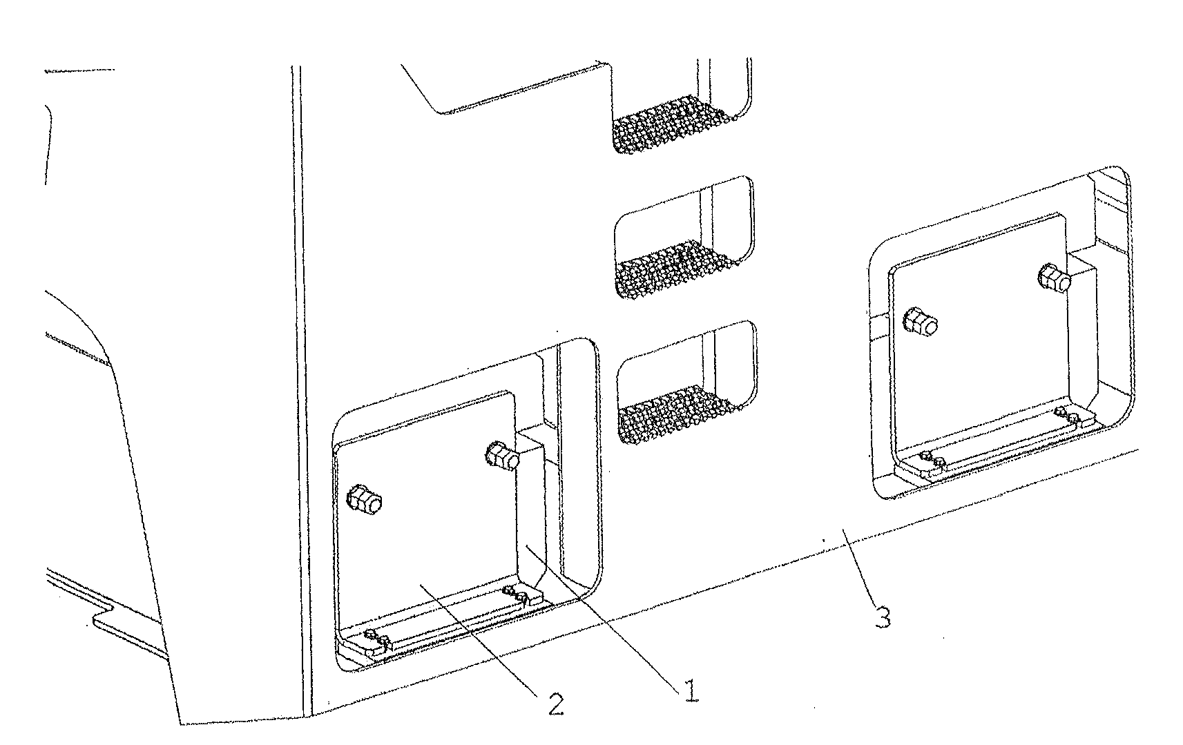
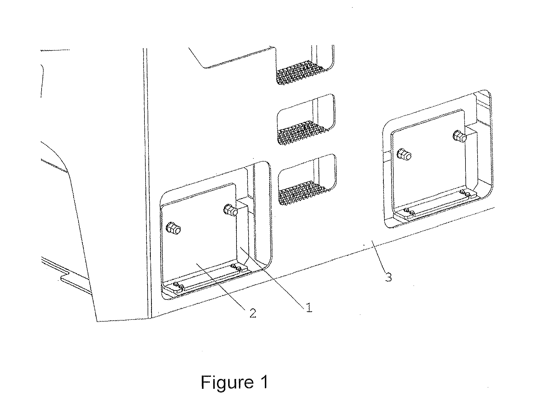
[0019]FIG. 1 illustrates the main components of the machine weight regulation system of the present invention comprising one or more ballasts (1); a fastening system (2); and a machine (3) containing housings; which is capable of carrying a plurality of types of extra weight.

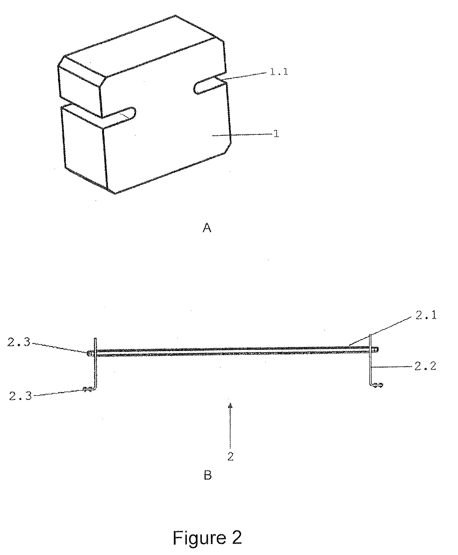
[0020]As can be seen in FIGS. 2 and 3, the one or more ballasts (1) are regular metallic solids of from 400 to 600 kgf weight each; comprise a width between 40 and 60% lower than the measured length; and a height corresponding to between 10 and 20% lower than the measured length.

[0021]The lateral cuts (1.1) are located between the midpoint of the faces and apex of the edges, being thus located above the center of gravity of the ballast (1). The fixing system (2) is inserted between the lateral cuts (1.1) of each ballast keeping them together and secured to the machine (3).

[0022]The side cut (1.1) also serve as support for the forks of the forklifts used in loading the ballasts (1) on the machine (3).

[0023]Prefer...


PUM


Abstract

The present invention relates to machine weight regulation system which comprises one or more ballasts (1); a fastening system (2); and a machine (3) containing a housing; capable of carrying a plurality of types of extra weight.

Description

FIELD OF THE INVENTION[0001]The present invention relates to the field of construction; specifically, to the field of machines, tools, or auxiliary devices for preparing or distributing paving materials, for handling the placed materials or to form, consolidate or finishing a paving.STATE OF THE ART[0002]Soil compaction is the method of mechanically increasing the density of the soil. In construction, this is an important part of the building process.[0003]If performed improperly, it can give rise to a soil accommodation and cause unnecessary maintenance costs or even the loss of the structure. Almost all types of building work sites and construction designs use mechanical compaction techniques.[0004]The desired level of soil compaction is best achieved by soil type combination with the appropriate compaction method. Factors, such as compaction specifications and site conditions of the work, should also be considered to choose the best type of soil compactor.[0005]The compactor roll...

Claims


Application Information

Patent Timeline
Patent Type & Authority Applications(United States)
IPC IPC(8): E01C19/22B62D49/08B66F9/075E02F9/18
CPCE01C19/22B66F9/07554B62D49/085E02F9/18E01C19/23E02D3/026E02D27/44E01C19/00
Inventor DE SYLOS, ALEXANDRE BIONDI
Owner ATLAS COPCO CONSTR TECHN BRASIL
Learn More