Interactive leg guide for offshore self-elevating unit

a self-elevating unit and leg guide technology, applied in the field of offshore structures, can solve the problems of buckling of braces, affecting the stability of the leg, and the bending moment of the legs between the upper and lower guide plates, so as to reduce the horizontal bending load acting, maintain the hardness and strength of the contact surface, and reduce the stiffness of the contact surfa

Inactive Publication Date: 2006-03-16
OFFSHORE TECH DEVMENT PTE
View PDF8 Cites 8 Cited by
  • Summary
  • Abstract
  • Description
  • Claims
  • Application Information

AI Technical Summary

Benefits of technology

[0013] The first portion has a deflectable guide unit comprised of an edge guide plate, an attachment plate, and a compressible resilient member sandwiched between the two plates. The second portion has a face guide plate, which extends longitudinally along the leg chord at strategic locations to reduce the horizontal bending loads acting on the legs.
[0014] Introduction of the compressible member behind the edge guide plate allows to decrease stiffness of the contact surface, while maintaining hardness and strength of the contact surface of the edge guide plates. As the edge guide plate deflects, the increased bending profile allows more edge guide plates to be in contact with the rack at the same time. Provision of the compressible member allows for better load distribution along the longitudinal plane of the leg guide system.

Problems solved by technology

As a result, the legs between the upper and lower guide plates sustain a large bending moment.
Since the legs have truss structure, the braces tend to fail under compressive load that is built up due to the horizontal moment couple.
The industry understands that high compressive loads are undesirable as they result in buckling of the braces under severe environmental conditions.
This guide assembly is inefficient, as the generated high compressive loads located mainly between the upper and lower edge plates.
This constitutes a local failure within the system.
A premature load buckling of the brace eventually occurs.
This reaction generates high compressive loads in the bracing members, which results in failure of the brace by buckling.

Method used


Image

  • Interactive leg guide for offshore self-elevating unit
  • Interactive leg guide for offshore self-elevating unit
  • Interactive leg guide for offshore self-elevating unit

Examples


Embodiment Construction

[0021] Reference will now be made to the following detailed description, taken in conjunction with the accompanying drawings, wherein like parts are designated by like numerals.

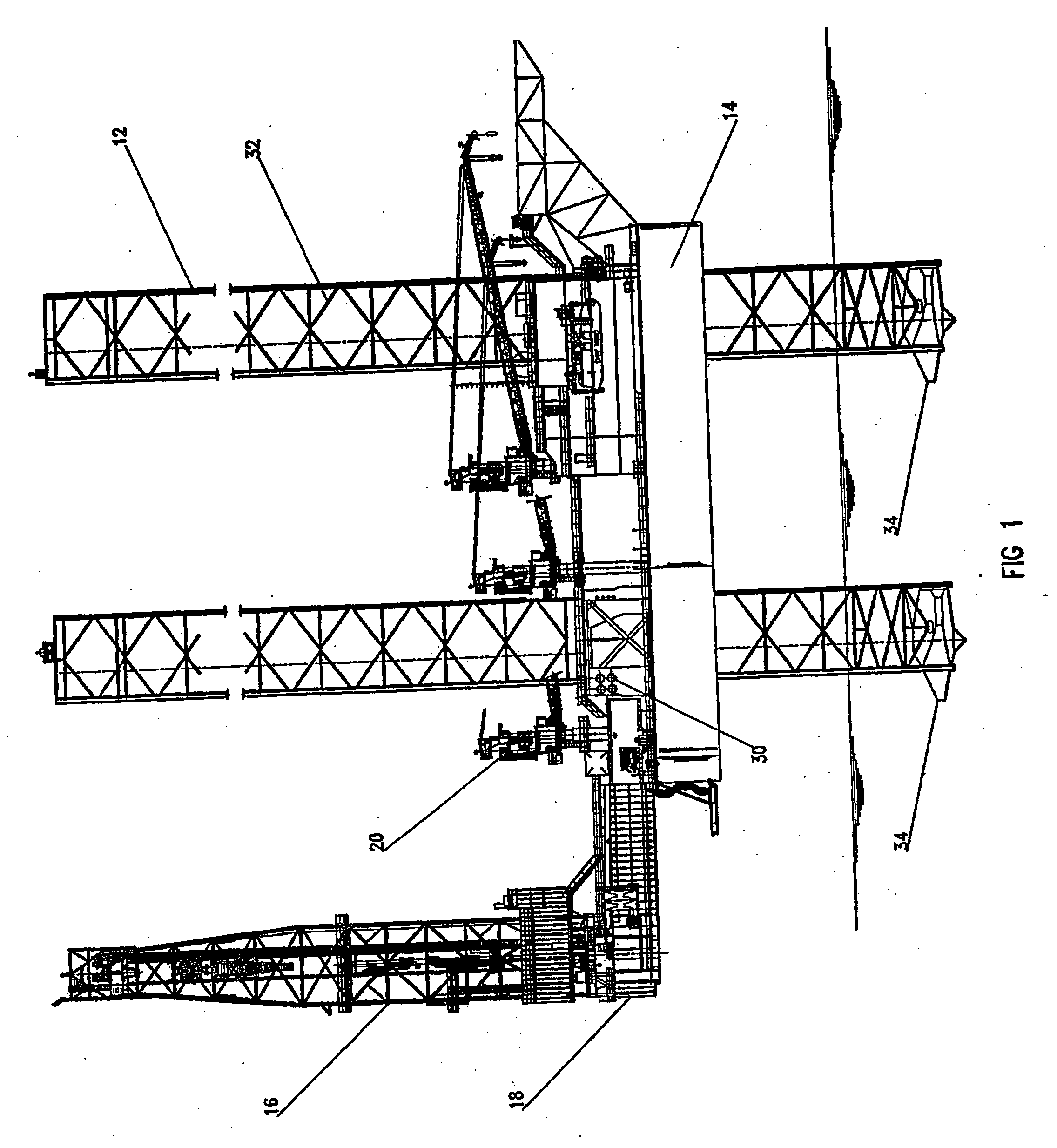
[0022] Referring now to FIG. 1, it shows a self-elevating jack-up unit. The jack-up unit is a mobile offshore structure that is used for mineral exploration and production. A typical jack-up unit is provided with a plurality of truss legs 12, which extend through openings in a floatable hull 14 of the jack-up unit. Although any number of legs may be used to support the hull 16, for illustration purposes, the jack-up rig shown in FIG. 1 has three such legs 12. The legs 12 are formed a system of horizontal and diagonal braces.

[0023] As the legs 12 are “jacked,” the hull 14 is elevated above an anticipated wave action to support the offshore exploration and / or production operations. Conventional offshore structures, such as the jack-up unit, are equipped with a derrick 16 mounted on the hull 14. The derrick 16...


PUM


Abstract

A leg guide for use in a leg of a jack up unit adapted to provide sliding guidance of the leg during vertical movement of the leg. The leg guide has a first portion contacting an edge of a leg chord and a second portion contacting a face of the leg chord along a longitudinal plane opposite the contact plane of the first portion. The edge contacting guide has a deflecting guide unit, which uses a compressible member sandwiched between two rigid plates. As the leg moves, the teeth of the leg chord contact the edge guide unit, with the compressible member absorbing compressible loads acting on the leg chord. The second portion provides for a face plate mounted transversely to the edge contacting guide for reducing the build-up of horizontal moment acting on the leg chord during the vertical movement of the leg and for reducing bending moments acting on the leg.

Description

BACKGROUND OF THE INVENTION [0001] This invention relates to offshore structures, and more particularly to offshore structures adapted for supporting oil and gas exploration / production operations at sea. Even more particularly, the invention relates to a type of an offshore structure known as a jack-up unit. A typical jack-up unit design uses a floatable hull with three or four supporting legs, which may be circular, square or triangular in cross-section, extending through the hull within leg guides. The legs may be built as truss units using a system of horizontal and diagonal braces. The legs support the hull during offshore operations, and are supported by the hull during transit. [0002] Once the platform is delivered to the desired location, the legs are lowered through openings in the hull to reach the seabed. The legs are secured to the bottom and then the hull is elevated to the operational height. The lowering and raising of the legs is performed by a plurality of jack-up as...

Claims


Application Information

Patent Timeline
Patent Type & Authority Applications(United States)
IPC IPC(8): E02B17/08
CPCE02B17/0818E02B17/08
Inventor FOO, KOK SENGQUAH, CHIN KAU MATTHEWCHAN, CHENG CHOONG
Owner OFFSHORE TECH DEVMENT PTE
Why Eureka
Try Eureka