Method for Producing an Assembly from an Energy Storage Module, and a Cooling Element and Assembly

Active Publication Date: 2016-11-03
BAYERISCHE MOTOREN WERKE AG
View PDF7 Cites 10 Cited by
  • Summary
  • Abstract
  • Description
  • Claims
  • Application Information

AI Technical Summary

Benefits of technology

[0027]The contact side of the cooling element and/or of the energy storage module is preferably cleaned beforehand in order to remove dirt particles, to improve the adhesion and thereby to prevent possible air locks.
[0028]After the high-voltage protective film has been adhesively bonded on, it is advantageous to clean and/or to activate the surface thereof in order to reduce air locks and to produce a better connection to the heat-conducting adhesive. The cleaning takes place, for example, with cleaning agents or solvents which remove contaminations of a chemical and mechanical type. For the activation, it is possible, for example, to perform a plasma treatment which improves the adhesion of an adhesive. Cleaning is also obtained here at the same time. The activation is preferably carried out after the film is adhesively bonded on and before the heat-conducting adhesive is applied to the film.
[0029]In order to position cooling element and energy storage module as a

Problems solved by technology

Air gaps between the energy storage module and the cooling element and unevennesse

Method used


Image

  • Method for Producing an Assembly from an Energy Storage Module, and a Cooling Element and Assembly
  • Method for Producing an Assembly from an Energy Storage Module, and a Cooling Element and Assembly
  • Method for Producing an Assembly from an Energy Storage Module, and a Cooling Element and Assembly

Examples


Example

DETAILED DESCRIPTION OF THE DRAWINGS

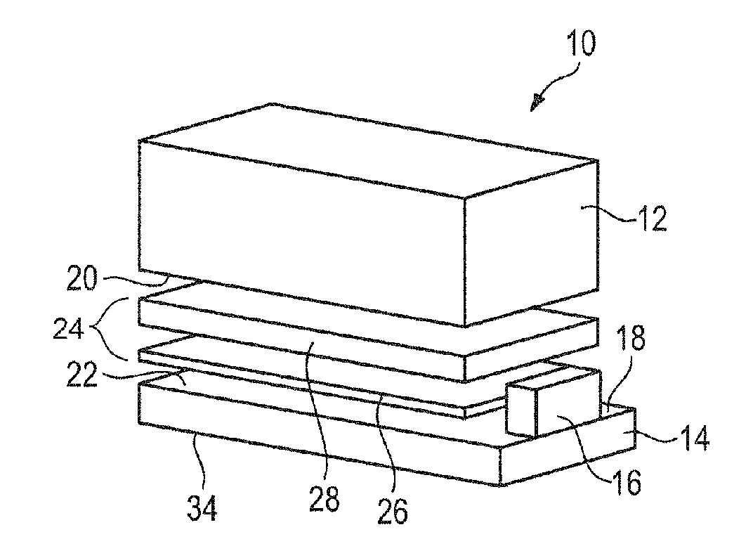
[0044]FIG. 1 shows an assembly 10 with an energy storage module 12 and a cooling element 14.

[0045]The energy storage module 12 is composed of a plurality of individual battery cells (not illustrated specifically here) which are interconnected electrically.

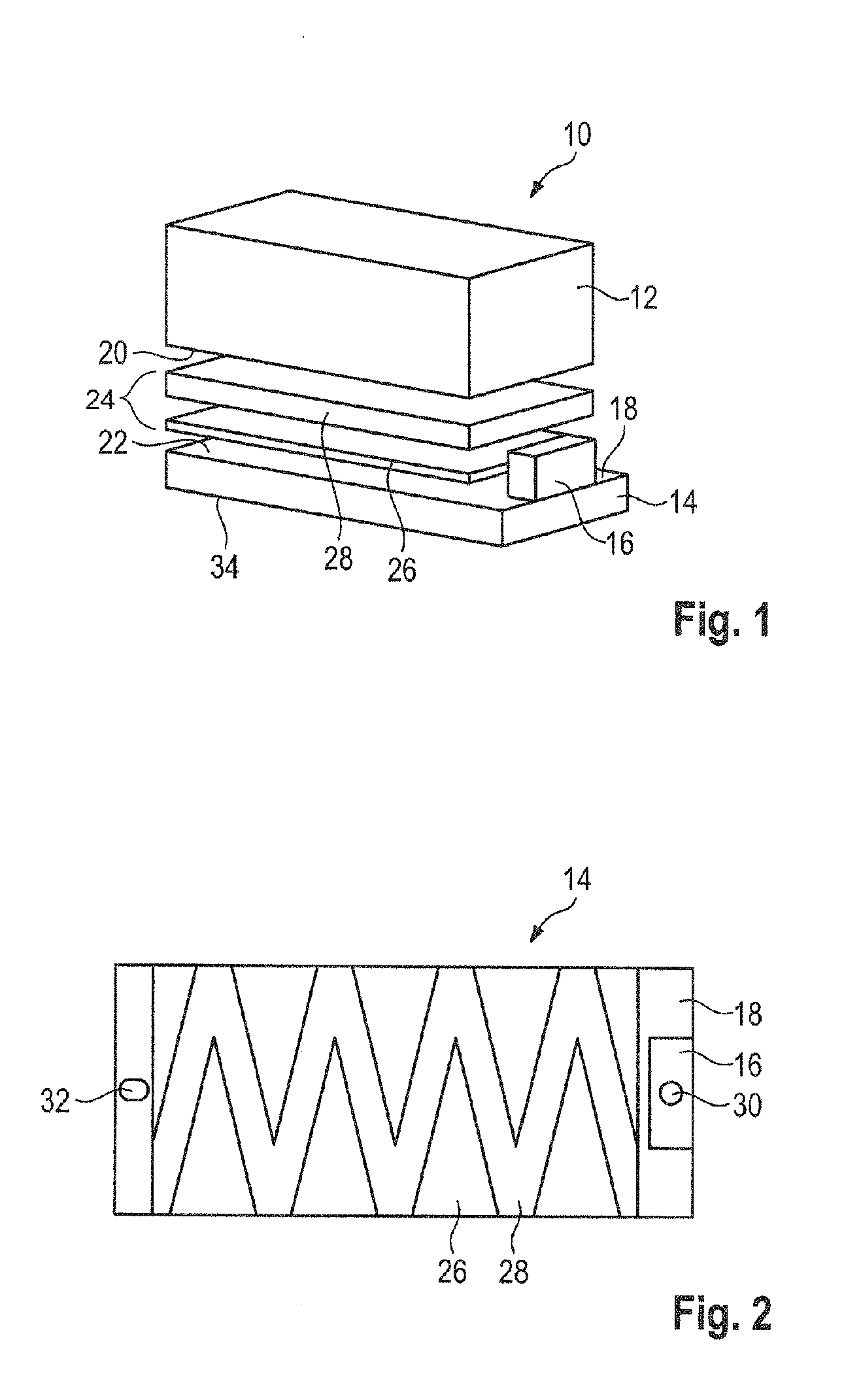
[0046]The cooling element 14 here is a rectangular cooling plate, in the interior of which are formed ducts (not shown) through which a suitable cooling fluid can flow. In this example, a fluid coupling flange 16 is arranged on the upper side 18 of the cooling element 14 at an end side. The fluid coupling flange 16 permits a fluid connection to the cooling ducts of the cooling element 14 and a flow connection with cooling elements of adjacent assemblies when the assembly 10 is installed in an overall energy store consisting of a plurality of assemblies 10 or in a vehicle.

[0047]The housing part of the energy storage module 12 that faces the cooling element 14 is composed here of a readily heat-con...


PUM


Abstract

A method is provided for producing an assembly for an energy supply system, having an energy storage module and a plate-shaped cooling element. Between a contact side of the energy storage module and a contact side of the cooling element, a deformable, adhesive heat conducting layer is applied. Subsequently, the energy storage module and the cooling element are pressed together, wherein by way of the heat conducting layer, a dimensionally stable adhesive connection between the energy storage module and the cooling element is produced, which permanently connects the energy storage module to the cooling element. By way of the adhesive connection, the contact side of the energy storage module is bonded with the contact side of the cooling element in a planar, material-fit, durable, and dimensionally stable manner such that the energy storage module and the cooling element form a structural unit.

Description

CROSS REFERENCE TO RELATED APPLICATIONS[0001]This application is a continuation of PCT International Application No. PCT / EP2015 / 052924, filed Feb. 12, 2015, which claims priority under 35 U.S.C. §119 from German Patent Application No. 10 2014 203 765.4, filed Feb. 28, 2014, the entire disclosures of which are herein expressly incorporated by reference.BACKGROUND AND SUMMARY OF THE INVENTION[0002]The invention relates to a method for producing an assembly for an energy storage system and to an assembly of this type.[0003]In the case of electrically operated vehicles, use is made of energy storage modules which each contain a plurality of individual battery cells combined to form a stack of battery cells. The stacks of battery cells are customarily braced in the manufacturing process by an encircling frame and retained in shape by the latter. The frame also serves for fastening the energy storage module to a housing or in a vehicle.[0004]In order not to exceed a maximum operating temp...

Claims


Application Information

Patent Timeline
IPC IPC(8): H01M10/625H01M2/10H01M10/6556H01M10/613H01M10/6551H01M50/204H01M50/231
CPCH01M10/625H01M10/613H01M10/6551H01M10/6556H01M2/1077H01M2/1083H01M2/1094H01M2220/20H01M10/653H01M10/6554H01M10/655Y02E60/10H01M50/24H01M50/204H01M50/231
Inventor LANDERER, FLORIANSIERING, SEBASTIANBURKART, FABIAN
Owner BAYERISCHE MOTOREN WERKE AG
Why Eureka
Try Eureka