
Cable Protection Device

Active Publication Date: 2016-11-03
DIALOG SEMICONDUCTOR
View PDF6 Cites 4 Cited by
  • Summary
  • Abstract
  • Description
  • Claims
  • Application Information

AI Technical Summary

Benefits of technology

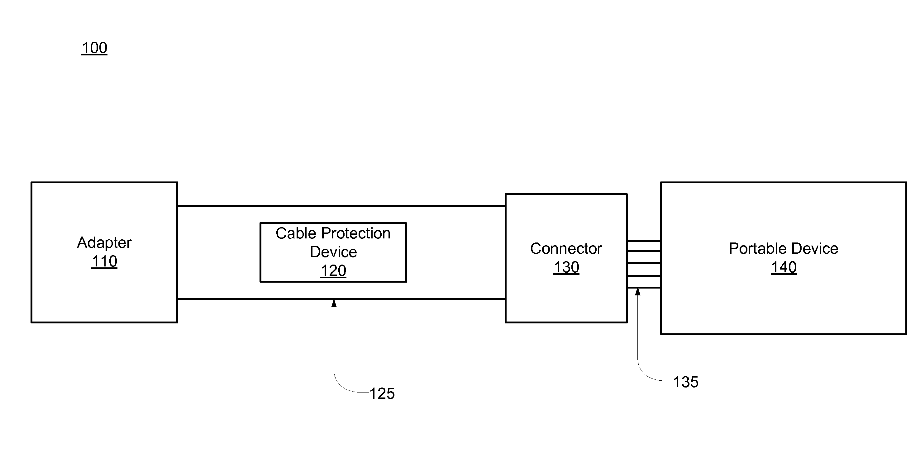
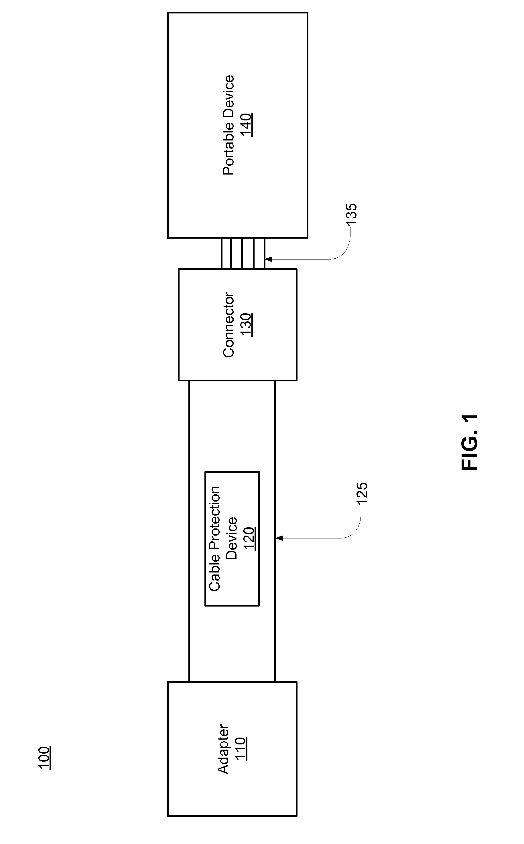
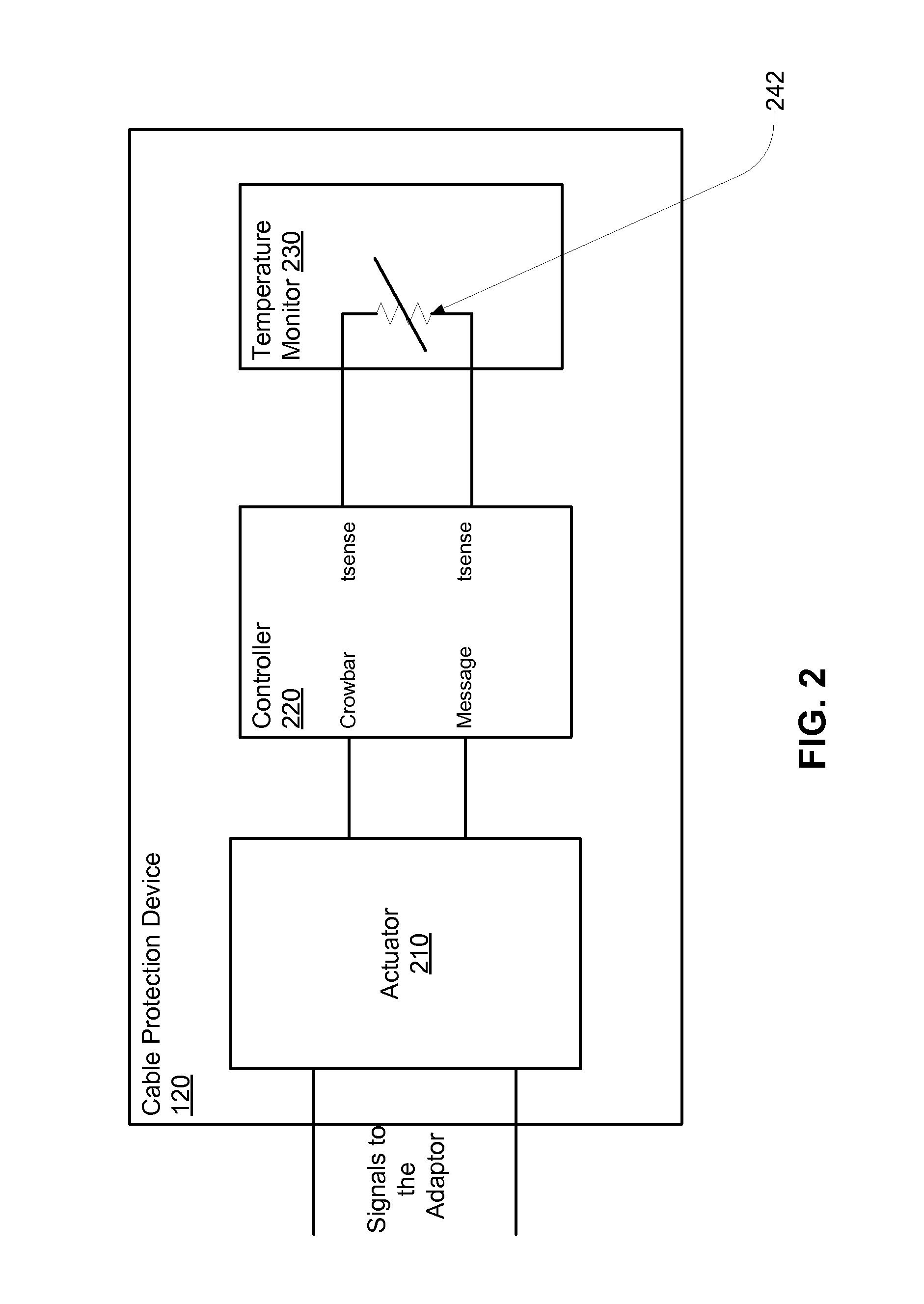
The cable protection device helps to prevent the device from overheating and burning out due to changes in temperatures. It uses a temperature monitoring device to continuously sense the temperature of the cable and device. When the temperature reaches a certain level, an alarm message is sent out and a control signal is sent to either an actuator circuit or a crowbar function circuit. The actuator circuit can lower the current limit to prevent overheating, while the crowbar function circuit can turn off power to the cable to prevent damage to the device or connector. Overall, this device helps to keep the device safe and functioning properly.

Problems solved by technology

The current supplied to the charging cable is high and creates a risk of the cable and connector overheating and burning out.
The protection devices are typically connected in series with the current path resulting in a high dissipation of power.
Additionally the protection devices are large, expensive, and slow leading to an inefficient protection device.

Method used


Image

  • Cable Protection Device
  • Cable Protection Device
  • Cable Protection Device

Examples


Embodiment Construction

[0011]The Figures (FIG.) and the following description relate to preferred embodiments of the present disclosure by way of illustration only. It should be noted that from the following discussion, alternative embodiments of the structures and methods disclosed herein will be readily recognized as viable alternatives that may be employed without departing from the principles of the present disclosure.

[0012]Reference will now be made in detail to several embodiments of the present disclosure, examples of which are illustrated in the accompanying figures. It is noted that wherever practicable similar or like reference numbers may be used in the figures and may indicate similar or like functionality. The figures depict embodiments of the present disclosure for purposes of illustration only. One skilled in the art will readily recognize from the following description that alternative embodiments of the structures and methods illustrated herein may be employed without departing from the p...


PUM


Abstract

One embodiment of a disclosed cable protection device connected between the positive and negative wires of the cable that provides an efficient method of protection from overheating of the device due to changes in temperatures with minimal power dissipation. The cable protection device includes a temperature monitoring device that continuously senses the temperature of the cable and device to check for overheating. A controller connected to the temperature monitor sends out an alarm message and a control signal to either an actuator circuit or a crowbar function circuit. The actuator circuit can send out current pulses to the adapter indicating the adapter to lower its current limit, so that the device can still keep charging and is not over heated. The crowbar function circuit causes the adapter to turn off power to the cable in order to provide burning of the device or connector due to overheating.

Description

BACKGROUND[0001]1. Technical Field[0002]The present disclosure relates to a power supply cable protection device for preventing a thermal runaway when connected to a portable device.[0003]2. Description of the Related Art[0004]Charging cables such as USB cables are widely used to connect AC adapter to a portable device for the purpose of charging the device battery. The current supplied to the charging cable is high and creates a risk of the cable and connector overheating and burning out. A protection device is embedded in the charging cable but the available protection devices shut off the power supply to the cable in case of a minor increase in the cable temperature. The protection devices are typically connected in series with the current path resulting in a high dissipation of power. Additionally the protection devices are large, expensive, and slow leading to an inefficient protection device.SUMMARY[0005]A cable protection device connected between the positive and negative wir...

Claims


Application Information

Patent Timeline
IPC IPC(8): H02H3/02H01R24/60
CPCH02H3/025H01R2107/00H01R24/60H02H7/001H02J7/00H02J7/0029H01R13/7137H02H5/043
Inventor ZAIDI, ATHARMALININ, ANDREY B.
Owner DIALOG SEMICONDUCTOR
Learn More