Image pickup apparatus that is capable of bounce emission photographing, control method therefor, and storage medium storing control program therefor
a pickup apparatus and image technology, applied in the field of illumination control, can solve the problems of excessive light amount, error in setting the bounce angle, and inability to accurately measure the distance measurement data obtained by the pre-emission, and achieve the effect of accurately setting the bounce angl
- Summary
- Abstract
- Description
- Claims
- Application Information
AI Technical Summary
Benefits of technology
Problems solved by technology
Method used
Image

Examples
first embodiment
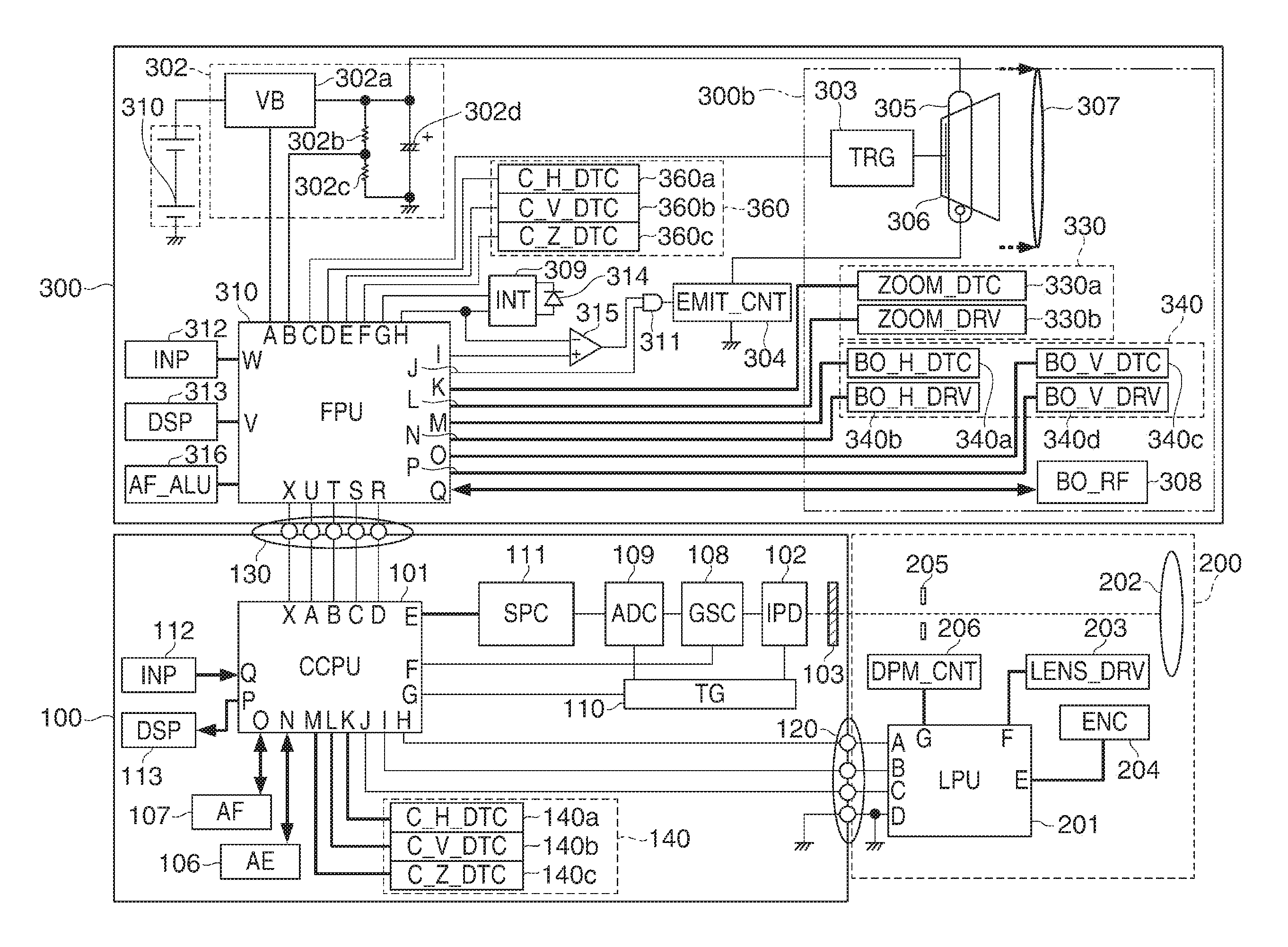
[0042]FIG. 1 is a block diagram schematically showing a configuration of an image pickup apparatus according to the present invention.
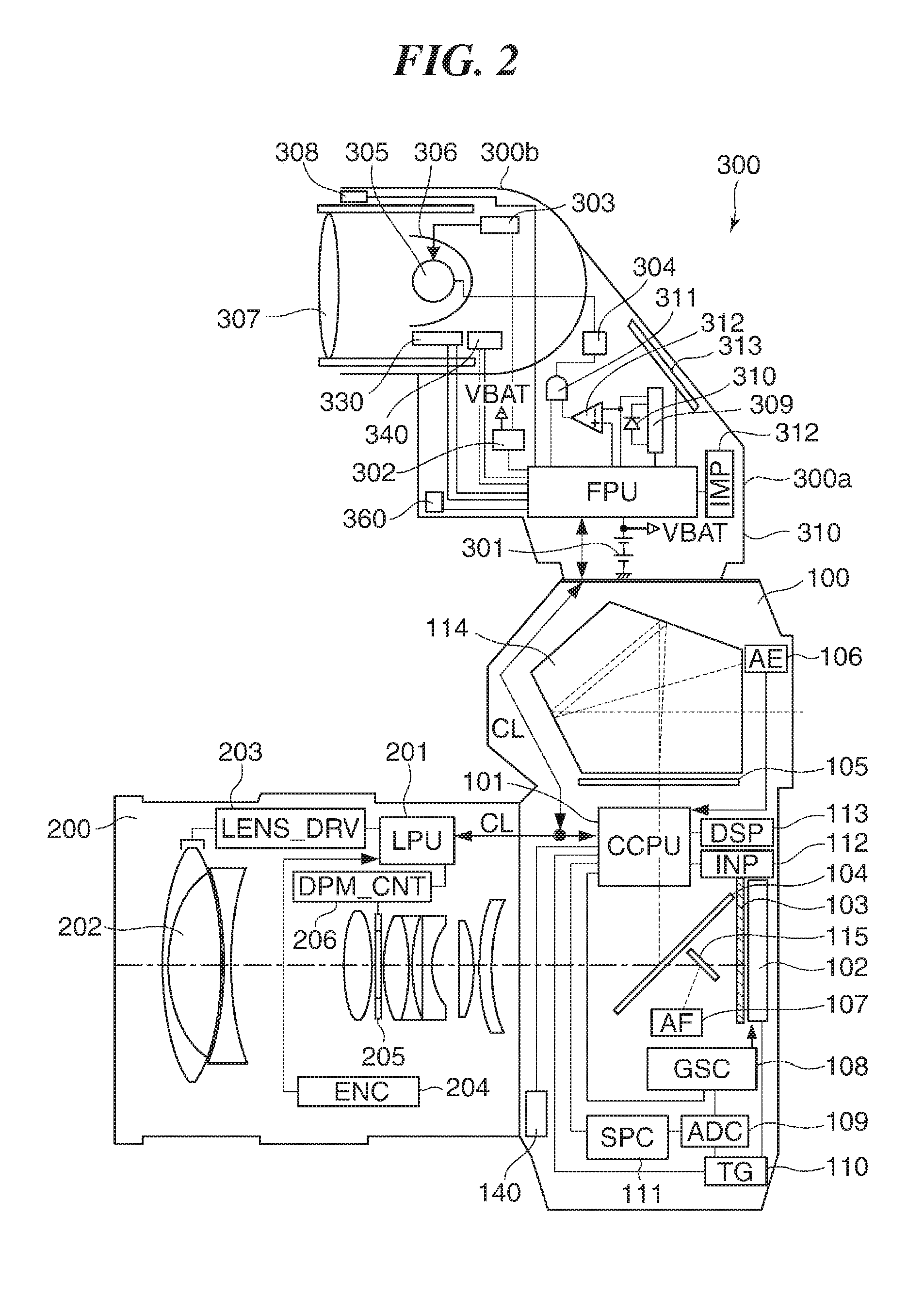
[0043]FIG. 2 is a view schematically showing the image pickup apparatus according to the first embodiment of the present invention in a broken state.
[0044]The image pickup apparatus shown in FIG. 1 and FIG. 2 is a digital camera (hereinafter referred to as a camera, simply) that has a camera body (an image pickup apparatus body) 100. Then, the camera body 100 is equipped with a photographing lens unit (hereinafter referred to as a lens unit, simply) 200 detachably. That is, the lens unit 200 is attachable to the camera body 100.
[0045]Moreover, the camera body 100 is equipped with a strobe (an electronic flash) 300 that is a lighting device so that attachment and detachment are possible. That is, the strobe 300 is attachable to the camera body 100. Then, the camera body 100 is able to communicate with the lens unit 200 and the strobe 300 as mentioned l...
second embodiment
[0247]In the second embodiment, emission of the AF auxiliary light unit is determined according to an AF auxiliary light emission instruction in a case where the strobe 300 performs the pre-emission control process. Then, the pre-emission operation is prohibited during the emission of the AF auxiliary light and in a predetermined period after the emission.
[0248]FIG. 18 is a flowchart showing an auto bounce emission photographing process performed with the camera according to the second embodiment of the present invention. It should be noted that steps in FIG. 16 that are the same as the steps in FIG. 4 are indicated by the same reference numbers and the descriptions thereof are omitted.
[0249]When determining that the auto bounce operation is performed in the step S11, the camera microcomputer 101 transmits a bounce start instruction to the strobe 300 through the communication line CL (step S1812). When receiving the bounce start instruction, the strobe microcomputer 310 performs the...
third embodiment
[0264]In the third embodiment, when the strobe 300 performs a pre-emission control process, it is determined whether the focusing-purpose distance measuring unit is in a charge storage operation by two-way communications between the camera body 100 and the strobe 300. Then, the pre-emission operation is prohibited when the focusing-purpose distance measuring unit is in the charge-storage operation.
[0265]FIG. 21 is a flowchart showing a bounce process performed with the camera according to the third embodiment of the present invention. It should be noted that steps in FIG. 21 that are the same as the steps in the flowchart in FIG. 9 are labeled by the same reference numerals, and their descriptions are omitted.
[0266]When the auto bounce is possible (YES in the step S702), the strobe microcomputer 310 receives “CS192 command: data X” shown in FIG. 7C from the camera microcomputer 101 (step S2103). Then, the strobe microcomputer 310 determines whether the focusing-purpose distance meas...
PUM
 Abstract
Description
Claims
Application Information
 - R&D
- Intellectual Property
- Life Sciences
- Materials
- Tech Scout
- Unparalleled Data Quality
- Higher Quality Content
- 60% Fewer Hallucinations
Browse by: Latest US Patents, China's latest patents, Technical Efficacy Thesaurus, Application Domain, Technology Topic, Popular Technical Reports.
© 2025 PatSnap. All rights reserved.Legal|Privacy policy|Modern Slavery Act Transparency Statement|Sitemap|About US| Contact US: help@patsnap.com