Comminuting unit for a comminuting device for comminuting feed material, in particular knife basket

Active Publication Date: 2016-11-10
PALLMANN MASCHFAB GMBH & CO KG
View PDF9 Cites 3 Cited by
  • Summary
  • Abstract
  • Description
  • Claims
  • Application Information

AI Technical Summary

Benefits of technology

The present invention provides a comminuting unit for comminution devices that ensures high chip quality while being cost-effective to operate. The invention achieves this through a detachable parts system for the receiving area of a knife assembly that allows for targeted replacement of parts based on wear. The clamping strip takes on a double function of tensioning the knife assembly against the receiving strip and providing wear protection for the blade support. A receptacle structured in several detachable parts results in compensating for dimensional tolerances that may occur by adjusting the blade supernatant and ensuring high chip quality.

Problems solved by technology

A receptacle structured in several detachable parts, however, results in that the dimensional tolerances of the individual parts add up and in their sum change the geometry of the receptacle.

Method used


Image

  • Comminuting unit for a comminuting device for comminuting feed material, in particular knife basket
  • Comminuting unit for a comminuting device for comminuting feed material, in particular knife basket
  • Comminuting unit for a comminuting device for comminuting feed material, in particular knife basket

Examples


Embodiment Construction

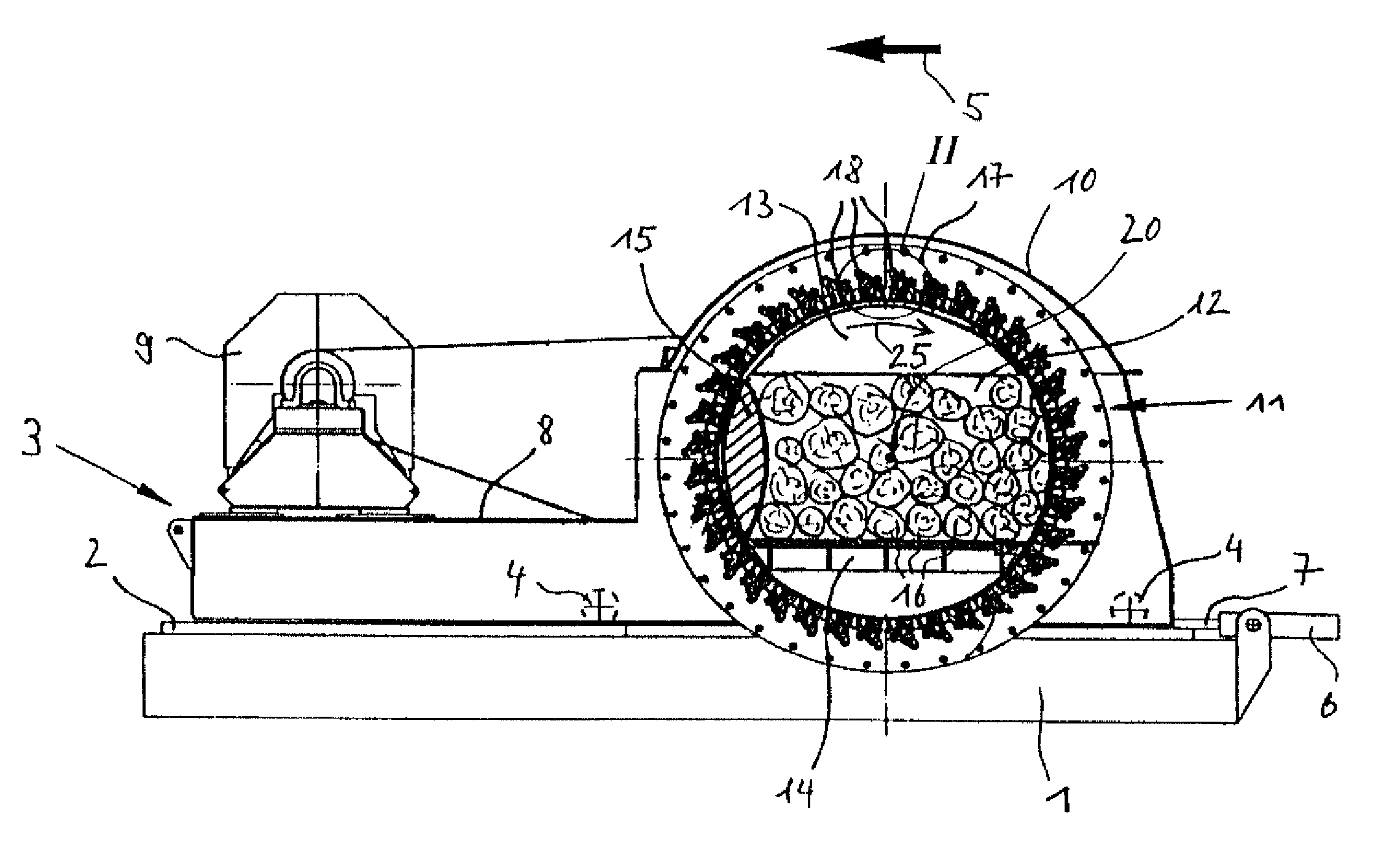
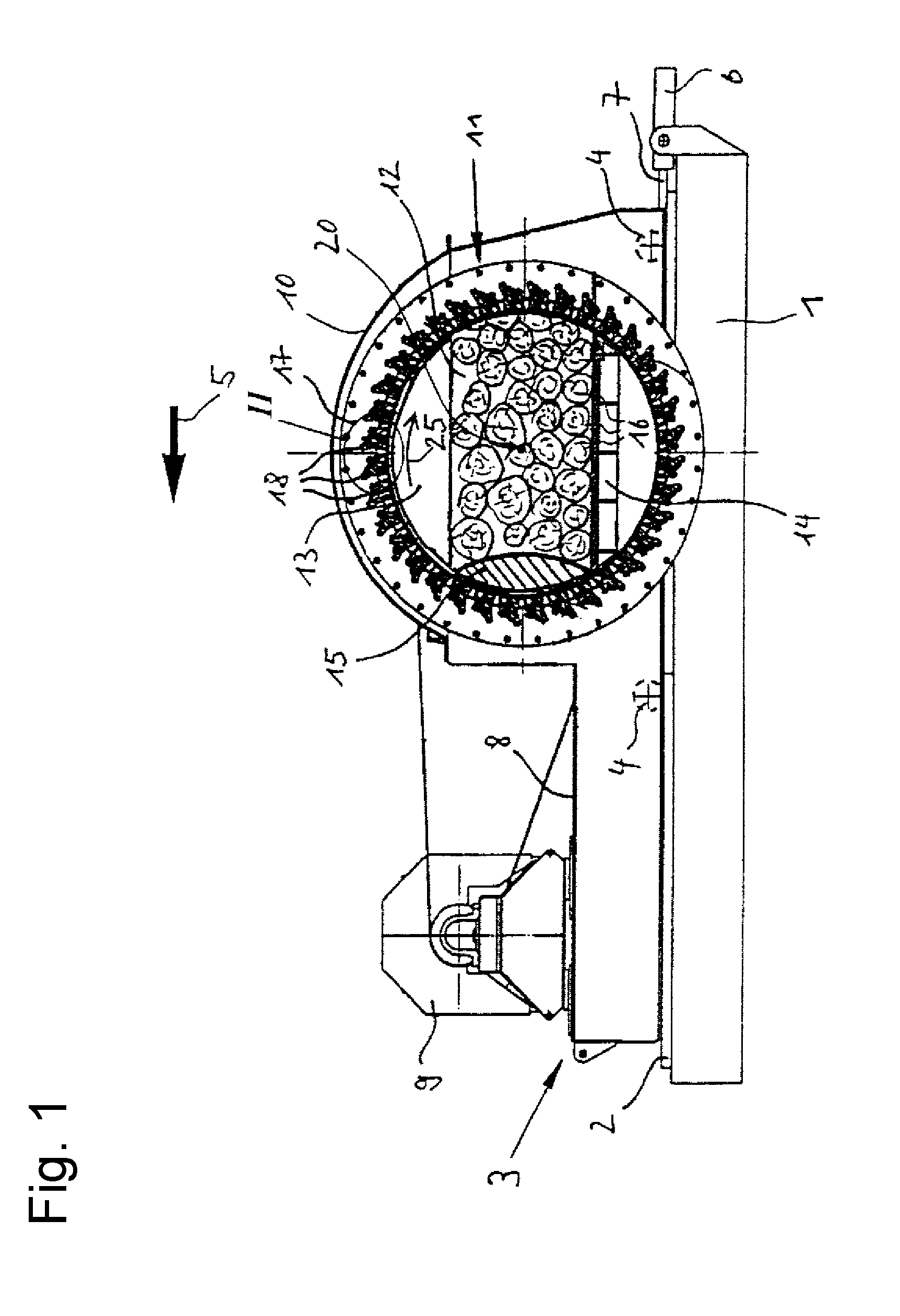
[0033]FIG. 1 illustrates a vertically guided longitudinal section through a long log flaker. One first sees a stationary base 1, at which upper side rails 2 are arranged which extend on display level. The rails 2 serve as a track for a machine base frame 3, which is transversely displaceably arranged on the wheels 4 in the direction of the arrow 5. A cylinder-piston unit 6, whose movable piston 7 acts on the machine base frame 3 and so provides the transverse movement of the machine base frame 3, is fixedly connected to the base 1. The machine base frame 3 also has a platform 8, which supports an electric motor 9.

[0034]Further, a dome-shaped housing 10 is secured to the machine base frame 3, which serves for the reception of a knife basket 11 that is freely rotatable about a horizontal axis 20. While the rear wall of the housing 10 is closed and is used to mount the drive shaft of the knife basket 11, the front face of the housing 10 has a circular opening through which a comminutin...


PUM


Abstract

A comminuting unit for a comminuting device for comminuting feed material, in particular a knife basket, with a plurality of rod-shaped blade supports concentrically arranged about an axis, which at their ends are each rigidly connected with a support ring or supporting disc that are concentric to the axis. At least one of the blade supports has a receptacle for securing a knife assembly having a chipping blade, wherein the blades of all chipping blades have a common radial distance from the axis. Between the blade support and the knife assembly at least one adjusting device is provided, with which the radial distance is adjustable. The receptacle has a receiving strip and a clamping strip, which are mounted in axially parallel position detachably on the blade support, the knife assembly being tensioned against the receiving strip via the clamping strip.

Description

[0001]This nonprovisional application claims priority under 35 U.S.C. §119(a) to German Patent Application No. 10 2015 005 787.1, which was filed in Germany on May 9, 2015, and which is herein incorporated by reference.BACKGROUND OF THE INVENTION[0002]1. Field of the Invention[0003]The invention relates to a comminuting unit for a comminuting device for comminuting feed material.[0004]2. Description of the Background Art[0005]Such comminuting units are, for example, used in knife ring flakers with a fixed or rotating knife ring, where they serve especially for comminuting wood, which is fed as lumpy material in the form of logs or as pourable material in the form of chips. The chips thus produced serve among other things as a starting material for the production of OSB products or for the chipboard industry.[0006]Thus, from DE 101 25 922 A1, DE 10 2004 004 877 A1 and EP 0 775 043 B1, knife ring flakers are known, which have a knife ring freely rotating about an axis serving as a com...

Claims


Application Information

Patent Timeline
IPC IPC(8): B27L11/02B02C18/18B27G13/04
CPCB27L11/02B02C18/18B27G13/04B27L11/005B02C18/186
Inventor PALLMANN, HARTMUTDEGEL, VOLKER
Owner PALLMANN MASCHFAB GMBH & CO KG
Why Eureka
Try Eureka