Mobile offshore wind turbine

Inactive Publication Date: 2016-11-10
TING CHENG
View PDF20 Cites 2 Cited by
  • Summary
  • Abstract
  • Description
  • Claims
  • Application Information

AI Technical Summary

Benefits of technology

[0014]In a further embodiment, when the wind direction is not substantially parallel to the blade surface of the turbine blades, each turbine blade can be driven by the wind to further drive the column to generate electricity. More specifically, the sensing unit on each turbine blade is configured to transmit the detection signal to the control center to change the direction of the blade surface corresponding to the wind direction, so that the turbine blade can continuously rotate to drive the column to maximize electricity production.
[0015]According to the embodiments described above, the present invention has the following advantages: (i) the offshore wind turbine can be moved when the wind direction is substan

Problems solved by technology

It has become increasingly difficult to find suitable locations for the wind farms on land.
On many occasions, there has been a lot of opposition against placement of wind turbines due mainly to the noise produced by the wind turbines and aesthetic effects of the placement of wind turbines.
Furthermore, for wind turbines to be able work efficiently, a windy and open area free from trees and buildings etc. is needed which is not always readily available.
However, the offshore wind power is considered the most expensive energy generating technology due to the scale thereof.
For example, for non-floating offshore wind turbines, the offshore repair and maintenance costs are high due to travel, distance, downtime and removal of such foundations after closure and decommissioning of the wind farm.
Also, the non-floatin

Method used


Image

  • Mobile offshore wind turbine
  • Mobile offshore wind turbine
  • Mobile offshore wind turbine

Examples


Embodiment Construction

[0021]The detailed description set forth below is intended as a description of the presently exemplary device provided in accordance with aspects of the present invention and is not intended to represent the only forms in which the present invention may be prepared or utilized. It is to be understood, rather, that the same or equivalent functions and components may be accomplished by different embodiments that are also intended to be encompassed within the spirit and scope of the invention.

[0022]Unless defined otherwise, all technical and scientific terms used herein have the same meaning as commonly understood to one of ordinary skill in the art to which this invention belongs. Although any methods, devices and materials similar or equivalent to those described can be used in the practice or testing of the invention, the exemplary methods, devices and materials are now described.

[0023]All publications mentioned are incorporated by reference for the purpose of describing and disclos...


PUM


Abstract

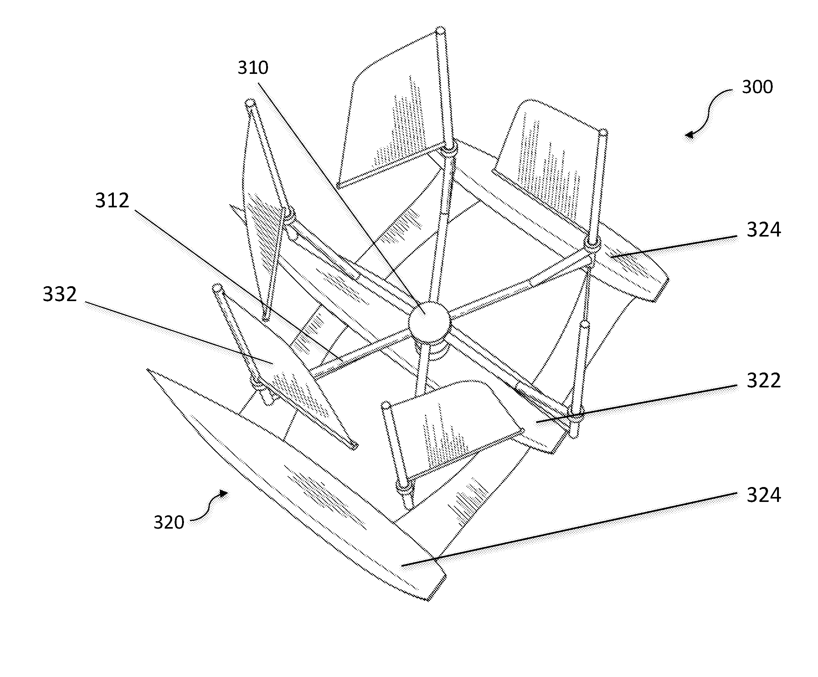
A mobile offshore wind turbine may include a column, a base and a plurality of turbine blades. In one embodiment, the column is at a center piece of the base and a plurality of connecting rods radially extending from the column to connect with the turbine blade. The base may also include a side piece disposed on both sides of the center piece to increase the stability of the base. The turbine blade has a blade surface that resembles the shape of a sail, and the turbine blade is rotatably disposed on the corresponding connecting rod and vertically aligned with the column. In another embodiment, a sensing unit may be disposed on the turbine blade to detect the direction of the wind and transmit the detection signal to a control center to further control the moving direction of the mobile wind turbine.

Description

CROSS-REFERENCE TO RELATED APPLICATIONS[0001]This application is a continuous-in-part (CIP) application of Ser. No. 14 / 283,240, filed on May 21, 2014 now pending, which is incorporated herein by reference.FIELD OF THE INVENTION[0002]The present invention relates to offshore wind turbines, and more particularly to mobile offshore wind turbines that can be moved when the direction of the wind changes to enhance the electricity generation efficiency.BACKGROUND OF THE INVENTION[0003]Offshore wind power refers to the construction of wind farms in bodies of water to generate electricity from wind. It has become increasingly difficult to find suitable locations for the wind farms on land. On many occasions, there has been a lot of opposition against placement of wind turbines due mainly to the noise produced by the wind turbines and aesthetic effects of the placement of wind turbines. Furthermore, for wind turbines to be able work efficiently, a windy and open area free from trees and buil...

Claims


Application Information

Patent Timeline
IPC IPC(8): F03D7/06B63B35/44F03D9/00F03D13/25F03D3/00F03D3/06
CPCF03D7/06F03D3/005F03D3/062G05D1/0206F03D13/25B63B35/44B63B2035/446F03D9/002Y02E10/74Y02E10/727F03D3/068F05B2240/93F05B2240/932B63B1/125B63B2001/123F03D9/25
Inventor TING, CHENG
Owner TING CHENG
Why Eureka
Try Eureka