Variable windmill wing wind power generator having power generation efficiency increasing means

A technology for wind turbines and power generation efficiency, which is applied to wind turbine components, wind engines, and wind engines at right angles to the wind direction. Such as convenient after-sales service, improved power generation efficiency, and high power generation efficiency

Inactive Publication Date: 2012-02-08
李仁南
View PDF3 Cites 8 Cited by
  • Summary
  • Abstract
  • Description
  • Claims
  • Application Information

AI Technical Summary

Problems solved by technology

[0010] However, although the above-mentioned "windmill 100 for wind power generators with deformable wings" of the above-mentioned published patent No. 10-2009-56280 depends on wind blowing to make the windmill wings 120 unfold or fold, when the windmill wings 120 move 90°, the windmill wings 120 are unfolded or folded. Folding will not only cause the windmill wing 120 to not fully unfold or not fully fold, but also hinder the rotation of the windmill 100 due to the elastic force of the sealing spring 137 that folds the windmill wing 120, so the power generation efficiency cannot be improved.
[0011] In addition, the above-mentioned published patent No. 10-2009-56280 "Windmill 100 for Wind Power Generator with Deformable Wings" is troublesome to maintain because it is not equipped with additional repairable parts.
That is, when one of the plurality of windmill blades 120 fails to operate due to failure, the windmill 100 still rotates with the wind, so it is difficult to stop the rotating windmill 100 to repair the faulty windmill blade 120
[0012] Moreover, the existing wind generators generate electricity by rotating only one turbine regardless of the wind force, so even if the wind becomes stronger, the power generation will not increase.

Method used


Image

  • Variable windmill wing wind power generator having power generation efficiency increasing means
  • Variable windmill wing wind power generator having power generation efficiency increasing means
  • Variable windmill wing wind power generator having power generation efficiency increasing means

Examples


Embodiment Construction

[0073] Hereinafter, preferred embodiments of a wind power generator equipped with a variable wind turbine blade according to the present invention will be specifically described with reference to the drawings.

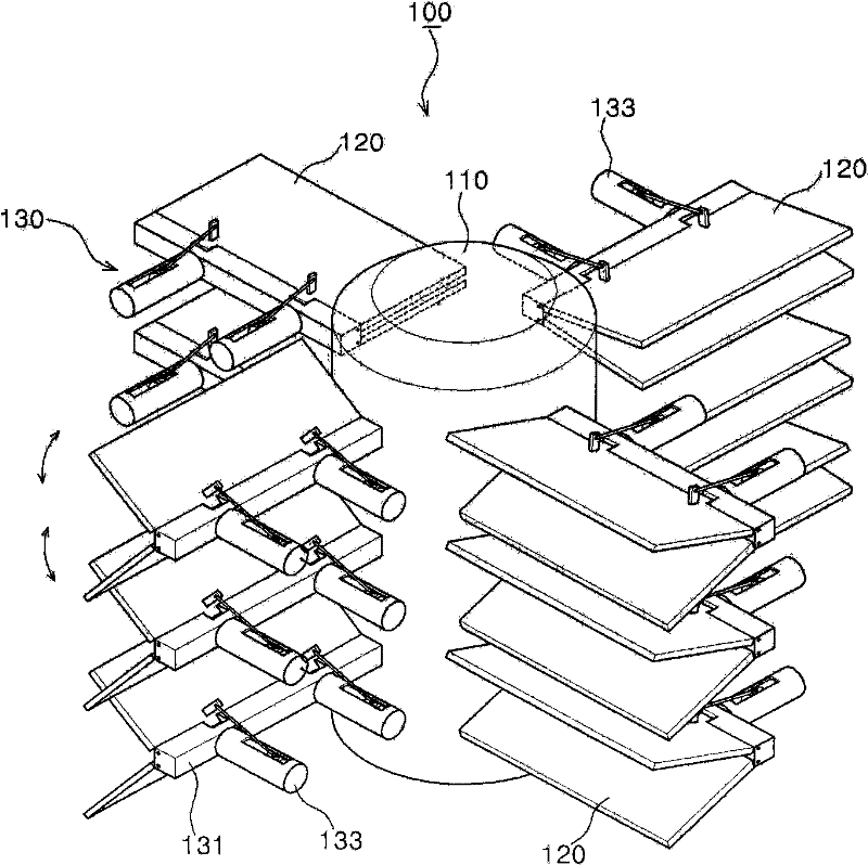
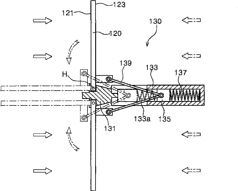
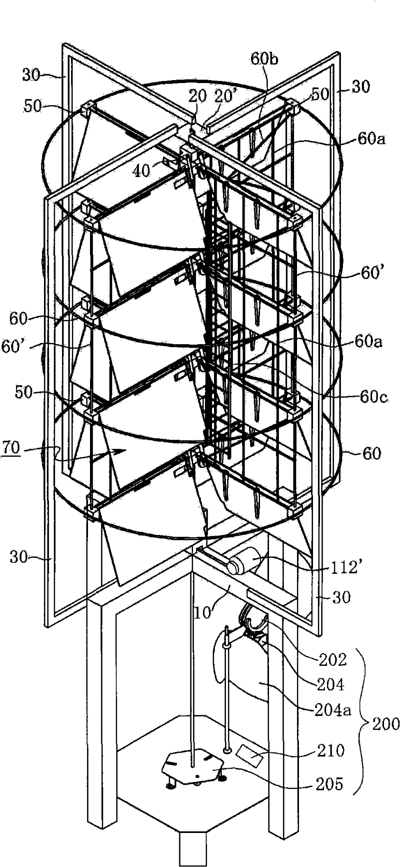
[0074] image 3 It is a perspective view of the variable windmill blade wind power generator equipped with power generation efficiency improving components of the present invention; Figure 4a It is a perspective view showing the installation state of the windmill blade of the present invention rotating in the clockwise direction; Figure 4b It is a perspective view showing the installation state of the windmill blade of the present invention rotating counterclockwise; Figure 5 It is a schematic diagram showing the support column structure connected and arranged on the same plane in the same group of the present invention; Figure 6 It is an exploded perspective view of the main parts of the variable windmill blade wind power generator equipped with power generation...


PUM


Abstract

The present invention relates to a variable windmill wing wind power generator having a power generation efficiency increasing means, which includes: an installation unit; a vertical rotating shaft; a bearing; '['-shaped holders; a plurality of inner wing installation units; support rods; a plurality of outer wing installation units; support rings; vertical support rods; support bars; a plurality of diagonal support bars connected between the upper and lower outer wing installation units within the same group; ladders; windmill wings; support units; a power generating means; a windmill wing fixing means; and a fixing means driving device. According to the present invention, the wind power generator can fold the windmill wings in the wind receiving direction and unfold the windmill wings when they are rotated by 180 DEG from the wind receiving direction so as to minimize a resistance force exerted on a rotary force of a windmill shaft, thus increasing the power generation efficiency. The wind power generator according to the present invention can simplify the manufacturing process by the simple structure and be installed in a plural number in various places regardless of the installation location, thus maximizing the amount of power generation per unit area, achieving the industrial purpose, and generating electricity in the environment-friendly fashion without causing pollution such as greenhouse gas. Also, the wind power generator according to the present invention can be installed in strong as a group with up / down multi-stages, stop easily the rotation operation of the windmill wings according to need, and reach easily a troubleshooter at the position of corresponding windmill wing which needs to repair, thus performing a follow-up control of maintenance conveniently.

Description

technical field [0001] The present invention relates to wind power generators, and in particular to variable wind turbine blade wind power generators equipped with components for improving power generation efficiency. Air resistance when the wings rotate to improve power generation efficiency, and drive multiple generators according to the wind force to improve power generation efficiency. In addition, it is not restricted by the setting place, is easy to set up, and can set up multiple windmill generators in a narrow space, so that the power production per unit area can be maximized, and industrialization can be realized. Background technique [0002] As the general power generation methods currently used, there are, for example, thermal power generation using a large amount of fossil fuels, atomic power generation using uranium, and hydropower generation requiring large-scale fresh water facilities. The main cause of warming may produce radioactive waste that is difficult...

Claims


Application Information

Patent Timeline
Patent Type & Authority Applications(China)
IPC IPC(8): F03D3/02F03D3/06F03D7/06F03D9/00F03D11/00
CPCF05B2240/202F03D3/068F03D3/02F05B2260/70Y02E10/74F05B2260/76Y02E10/28F05B2240/218F05B2240/211F03D3/005Y02E10/20Y02E10/728Y02P70/50F05B2240/31F03D13/20F03D15/10F03D80/70
Inventor 李仁南
Owner 李仁南
Why Eureka
Try Eureka