Self-priming centrifugal pump

Active Publication Date: 2016-11-10
ALFA LAVAL CORP AB
View PDF0 Cites 3 Cited by
  • Summary
  • Abstract
  • Description
  • Claims
  • Application Information

AI Technical Summary

Benefits of technology

The patent aims to improve the efficiency of self-priming centrifugal pumps that use a pump screw to feed gas to the pump's impeller when pumping liquid. The technical effect of the invention is to increase the efficiency of these pumps.

Problems solved by technology

Then the pump housing must be filled with liquid before the pump is started, otherwise the pump will not be able to function.
If the pump housing becomes filled with gases or vapors, the impeller becomes gas-bound and incapable of pumping the liquid.

Method used


Image

  • Self-priming centrifugal pump
  • Self-priming centrifugal pump
  • Self-priming centrifugal pump

Examples


Embodiment Construction

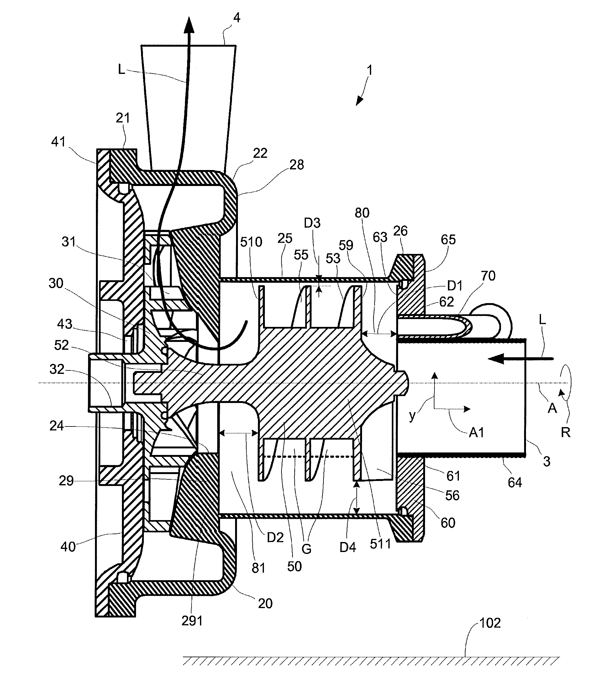
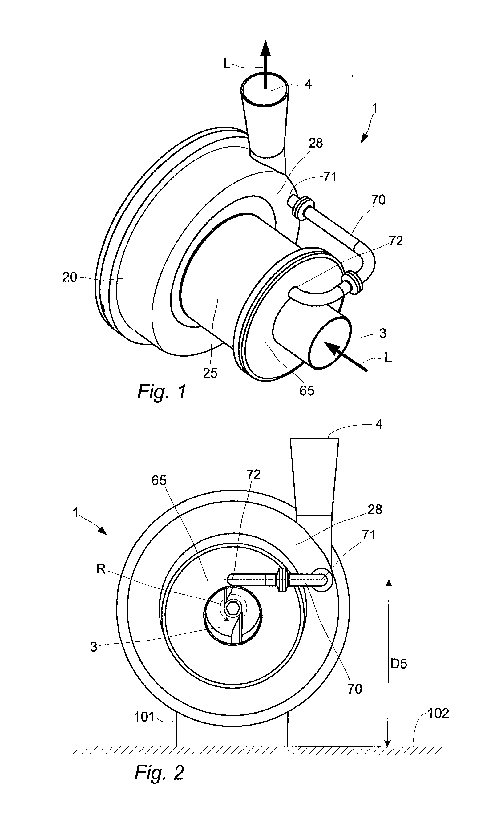
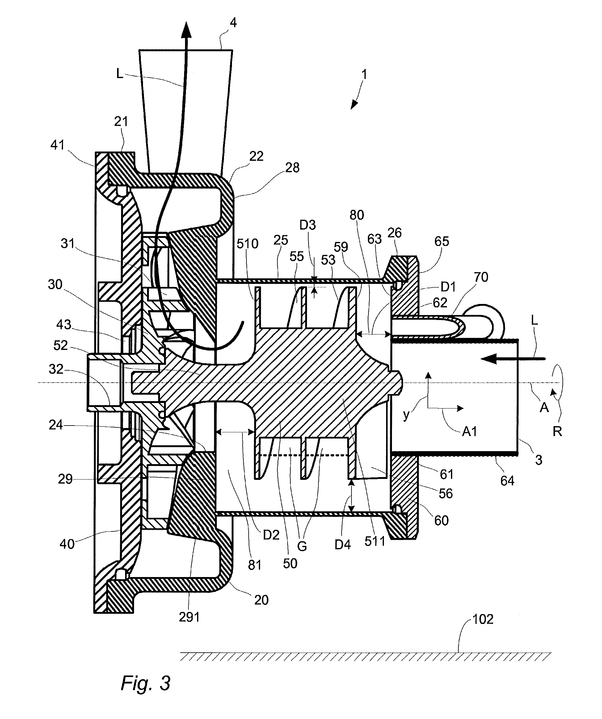
[0036]With reference to FIG. 1 a self-priming, centrifugal pump 1 is illustrated, which hereafter is referred to as pump 1. The pump 1 has a first housing part 25 and a second housing part 20. The first housing part 25 has an inlet 3 that is connectable to e.g. a pipe (not shown) for receiving a liquid L. The two housing parts 25, 20 are connected to each other such that the liquid L that enters the first housing part 25 via the inlet 3 flows from the first housing part 25 and into the second housing part 20. The liquid L exits from the second housing part 20 via an outlet 4 that is connectable to e.g. a pipe (not shown).

[0037]With further reference to FIG. 2, a return conduit 70 is connected from a side 28 of the second housing part 20 that faces the first housing part 25, to a side 65 of the first housing part 25 where the inlet 3 is arranged. The side 28 of the second housing part 20 where the return conduit 70 is connected is referred to as a front side 28 of the second housing ...


PUM


Abstract

A self-priming, centrifugal pump comprising a first housing part having a front wall with an inlet, a second housing part having an outlet, an impeller rotatably arranged in the second housing part and a pump screw rotatably arranged in the first housing part, connected to the impeller and comprising a center body around which a helical blade is arranged for feeding the impeller with any gas that is present in the liquid, wherein the center body is arranged at a distance from a side of the front wall that faces the center body, such that a channel with a width of at least 12 mm is formed between the center body and the side of the front wall that faces the center body.

Description

TECHNICAL FIELD[0001]The invention relates to self-priming centrifugal pumps that have one housing part for an impeller that pumps liquid and another housing part for a pump screw that feeds the impeller with liquid and any gas that is present in the liquid.BACKGROUND ART[0002]Today so called centrifugal pumps are used to transport liquids by the conversion of rotational kinetic energy to the hydrodynamic energy of the liquid flow. The rotational energy is typically generated by a motor. The pump has a housing, or casing, and an impeller is arranged inside the housing. The fluid enters the impeller along or near to a rotating axis of the impeller and is accelerated by the impeller, flowing radially outward towards an outlet of the housing, from where it exits.[0003]Most centrifugal pumps are not self-priming. Then the pump housing must be filled with liquid before the pump is started, otherwise the pump will not be able to function. If the pump housing becomes filled with gases or v...

Claims


Application Information

Patent Timeline
IPC IPC(8): F04D9/02F04D29/42F04D1/02F04D29/18F04D3/02F04D31/00
CPCF04D9/02F04D3/02F04D31/00F05B2240/14F04D29/181F04D29/426F05B2240/30F04D1/025F04D9/041
Inventor DAUGAARD, POUL ANTONRAABJERG JENSEN, JESPERREHHOFF, KENNETH
Owner ALFA LAVAL CORP AB
Why Eureka
Try Eureka