Pump arrangement for liquid tanks
- Summary
- Abstract
- Description
- Claims
- Application Information
AI Technical Summary
Benefits of technology
Problems solved by technology
Method used
Image

Examples
first embodiment
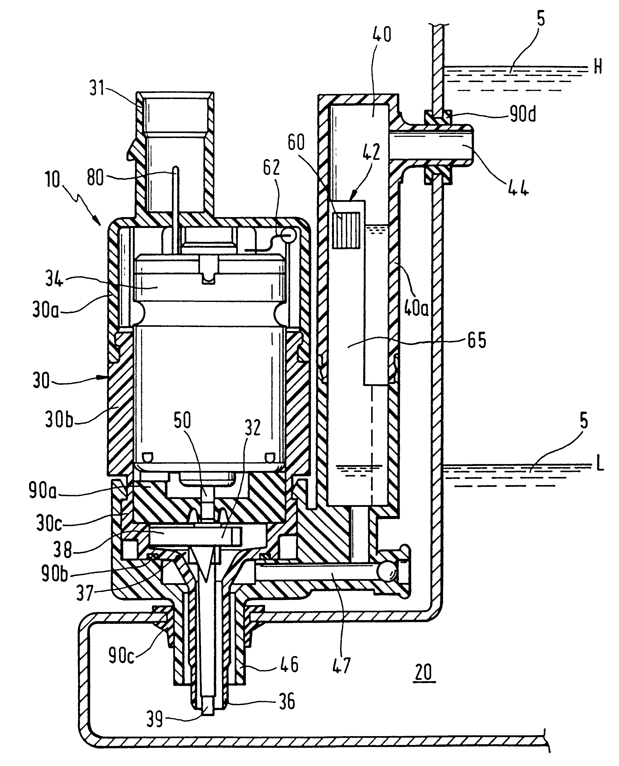
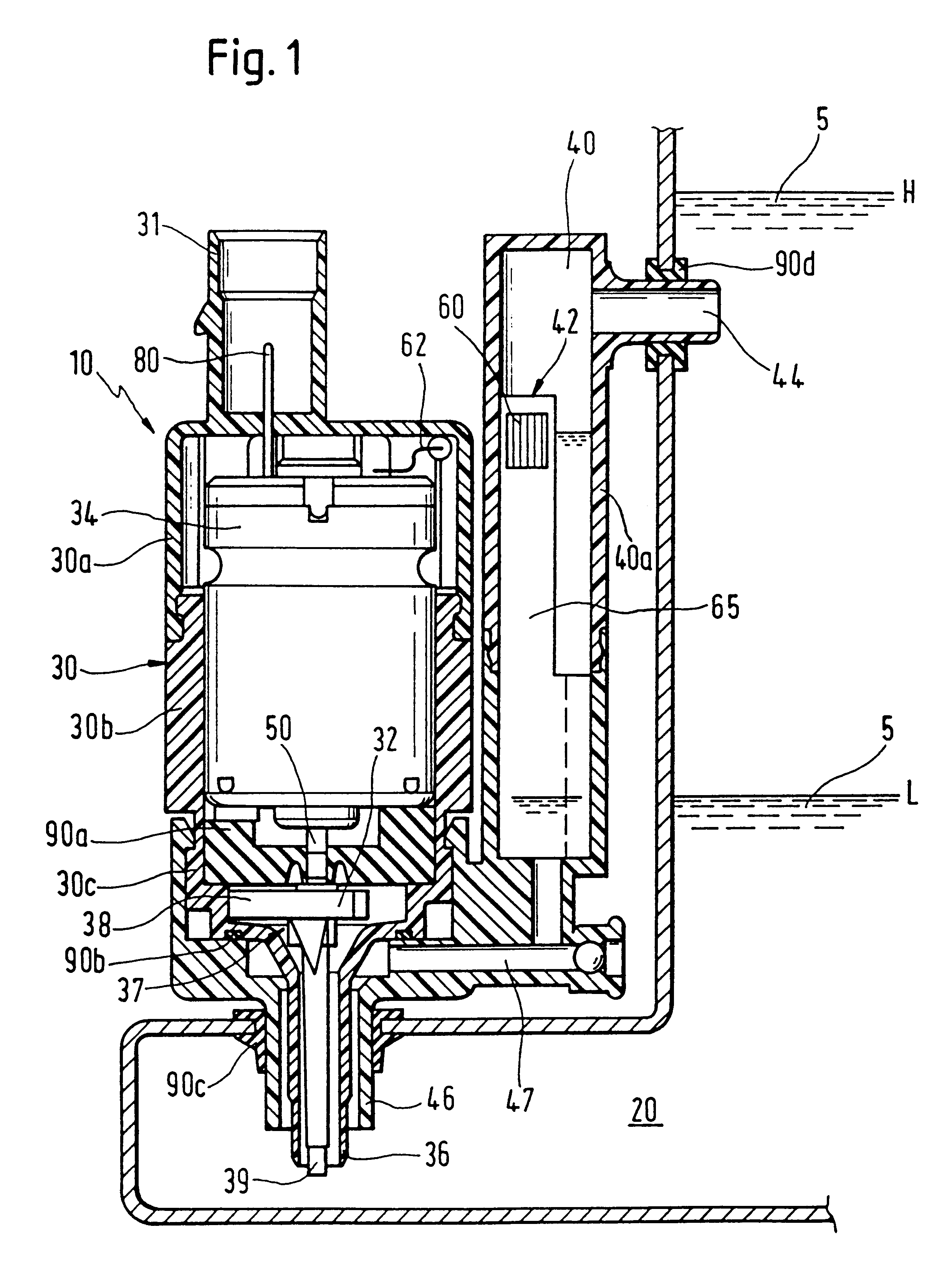
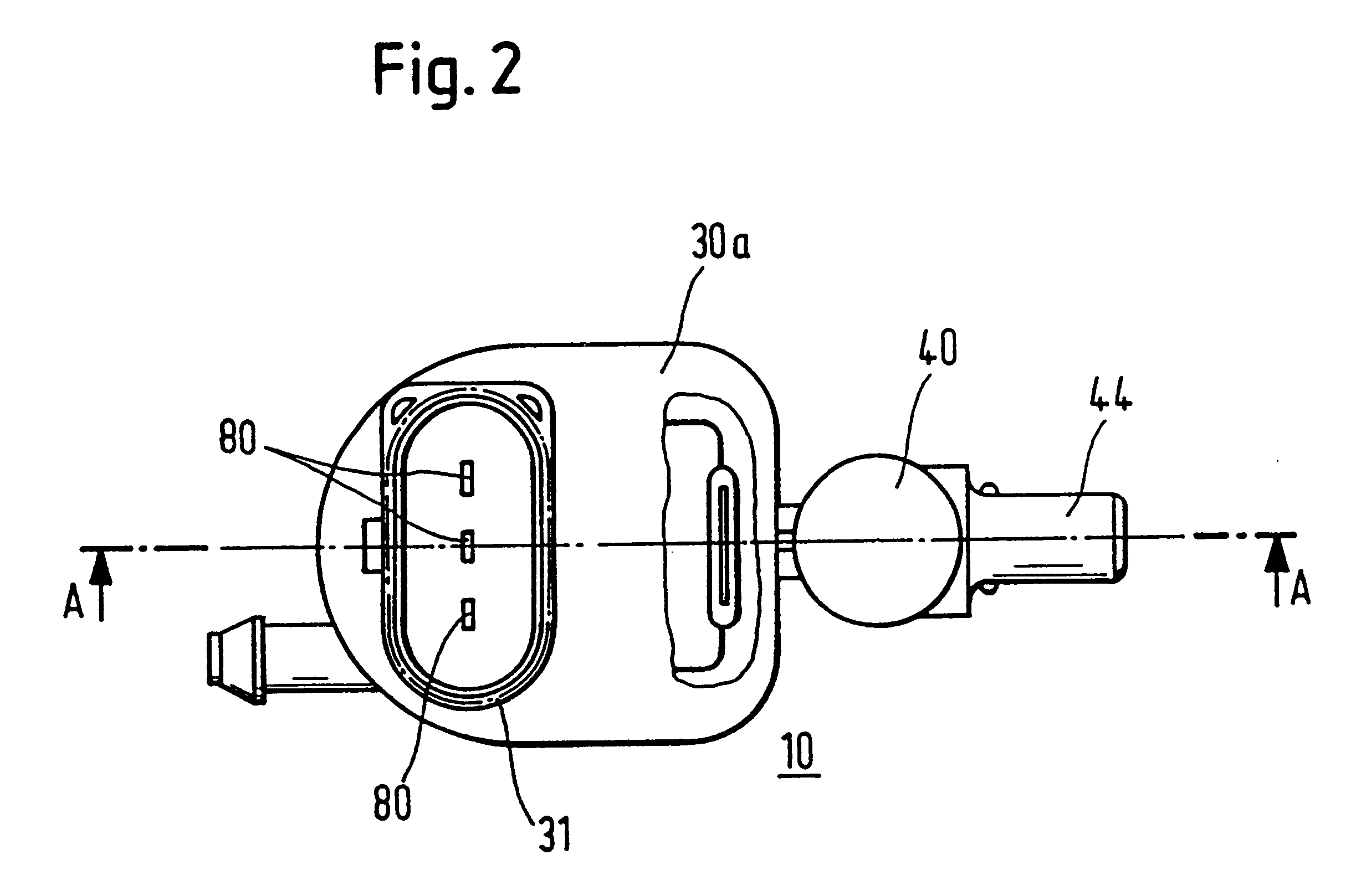
The first preferred embodiment of the pump arrangement 10 according to the invention is shown in longitudinal section in FIG. 1. The sectional view corresponds to section line A--A in FIG. 2, which shows a plan view of the pump arrangement 10 according to the invention in the
In FIG. 1, the pump arrangement 10 according to the invention is shown in the mounted state on a liquid tank 20. If the pump arrangement 10 according to the invention is used in a motor vehicle, the liquid tank 20 with the pump arrangement 10 is normally located in the engine compartment of the motor vehicle. Since the space requirement, on the one hand, and the costs, on the other hand, are of crucial importance in motor-vehicle construction, these aspects, in addition to the technical reliability, represent the main considerations for the present invention.
The liquid tank 20 (not fully shown) holds the liquid 5, which is delivered to the spray nozzles (not shown) by means of the pump arrangement. The liquid 5 ...
first embodiment 10
The first embodiment 10 according to the invention works as follows:
If the initially empty liquid tank 20 is filled with liquid 5, the sensor housing 40 fills up via the liquid outlet 46 (in this case acting as an inlet), in the course of which it is vented via the liquid 44. This continues until the sensor housing 40 is completely filled and the liquid tank 20 has reached a desired level, shown by way of example in FIG. 1 by the liquid level H. Since the float 65 has a lower specific density than the liquid 5, it is subjected to a buoyancy force until it comes to rest on the top boundary wall of the housing part 40a of the sensor housing 40. If the operator now actuates the pump arrangement, the motor 34 is electrified and the suction turbine is put into operation. By the rotational movement of the suction turbine, liquid 5 is extracted from the liquid tank 20 via the liquid inlet 36 and is fed through the liquid outlet 46 to the spray nozzle (not shown).
If the level in the liquid ...
second embodiment
The second embodiment differs from the first embodiment by the sensor arrangement 42'. Instead of a float, the second embodiment uses two electrodes 42A, 42B which, in the preferred embodiment, are in the form of two parallel, elongated rods. A voltage is applied to the two rods via the two allocated electrodes 80, which voltage leads to a voltage drop between the electrodes. If the two electrodes 42A, 42B are located in a sensor tank 40 filled with liquid 5, a certain first voltage drop V.sub.1 occurs as a result of the increased conductivity of the liquid 5. If the level in the liquid tank 20 falls to the critical level L, this leads to a situation in which there is no longer any liquid 5 between the electrodes 42A, 42B, as a result of which a voltage drop V.sub.2 occurs. The transition from the voltage drop V.sub.1 to the voltage drop V.sub.2 is detected by an electronic analysing means (not shown) and the corresponding warning signal "low-liquid level" is produced.
A third prefer...
PUM
 Abstract
Description
Claims
Application Information