Display device for holographic reconstruction

a display device and holographic reconstruction technology, applied in the field of holographic reconstruction, can solve the problems of insufficient holographic reconstruction of a preferably moving three-dimensional scene, the distance between the two spatial light modulators is much larger than the pixel pitch, and the requirements cannot be fulfilled in practi

Active Publication Date: 2016-11-10
SEEREAL TECHNOLOGIES
View PDF1 Cites 62 Cited by
  • Summary
  • Abstract
  • Description
  • Claims
  • Application Information

AI Technical Summary

Benefits of technology

[0025]Therefore, it is an object of the present invention to provide a display device which avoids the disadvantages of prior art display devices. Furthermore, the display device shall be designed adequately flat where a complex modulation of sufficiently coherent light has to be achieved to control the phase and the amplitude independently from each other in a spatial light modulator device.

Problems solved by technology

The modulation of only one value per pixel, i.e. a phase-only or an amplitude-only modulation, however only results in an insufficient holographic reconstruction of a preferably moving three-dimensional scene.
These combinations of two spatial light modulators which serve to achieve a complex-valued modulation have the disadvantage that the distance between the two spatial light modulators is much larger than their pixel pitch, i.e. the distance between two pixels.
When using imaging elements, there is the challenge that exactly one pixel of the first spatial light modulator must be imaged onto one pixel of the second spatial light modulator across the entire surface of the spatial light modulators.
Such requirements can hardly be fulfilled in practice.
Cross-talking can be even worse if the two spatial light modulator panels, the optical imaging system or the light sources are not perfectly aligned in relation to each other.
Furthermore, if spatial light modulator panels are combined and disposed very close to each other, such arrangements are susceptible to errors when diffraction of the incident wave field will take place at the first plane of diffracting apertures, which is e.g. a phase spatial light modulator forming the first plane of the sandwich-type complex spatial light modulator.
This crosstalking deteriorates e.g. the reconstruction quality of a holographic display device because this corresponds with a wrong combination of amplitude and phase values when complex values are represented by the spatial light modulators.
And even an angular tolerance of 0.5° deg requires significant technical effort if realized at a display size area and with a prism spacing of <100 μm.

Method used


Image

  • Display device for holographic reconstruction
  • Display device for holographic reconstruction
  • Display device for holographic reconstruction

Examples


Embodiment Construction

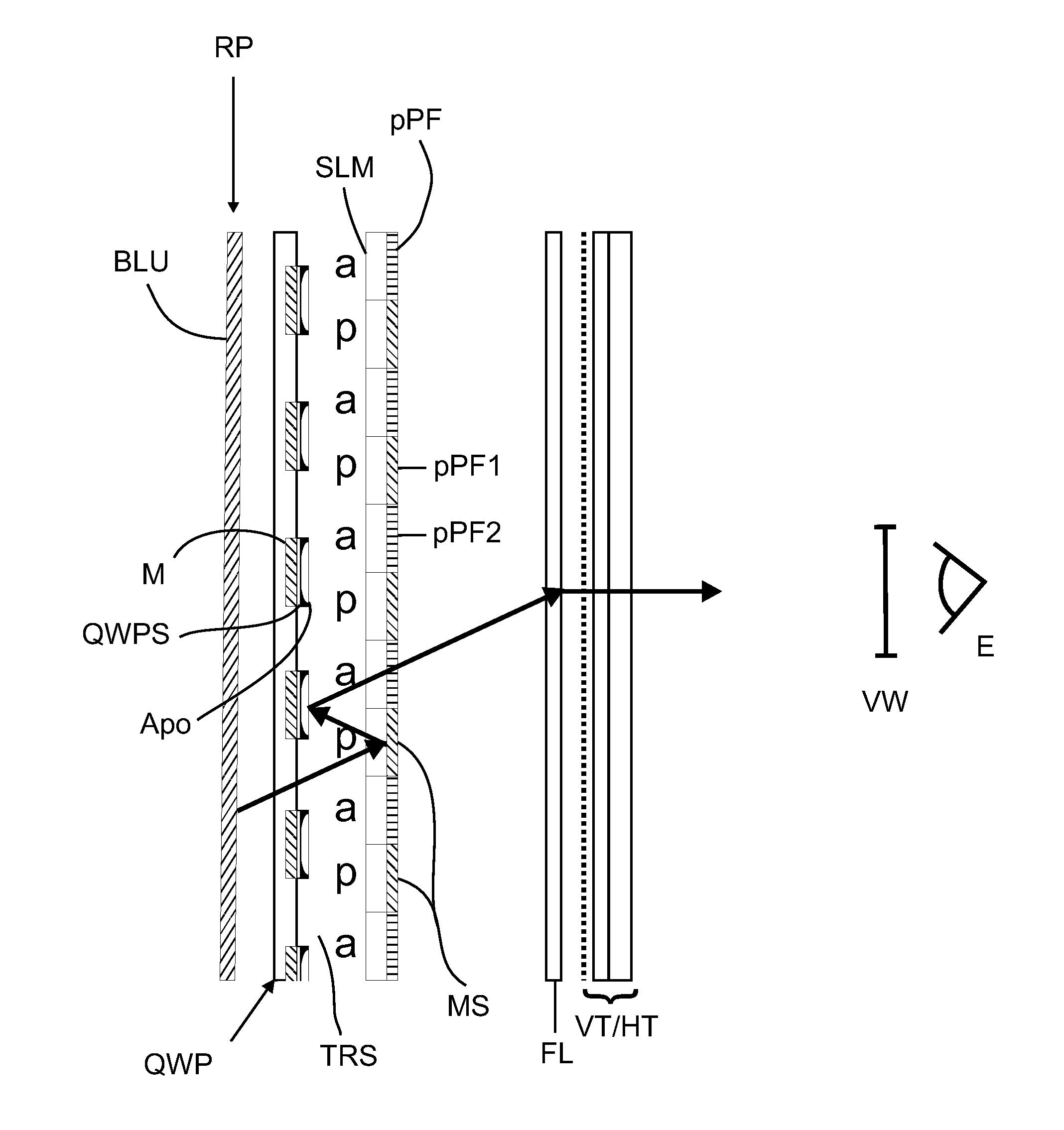
[0137]Like reference designations denote like components in the individual figures and accompanying description. In the following, the designations “in front of” and “behind” e.g. in front of the spatial light modulator device mean the light seen in regards to the propagation of the light.

[0138]The illumination unit can contain several specific modifications to be used preferably within a holographic display device. The illumination unit can be used for coherent light and for light which only shows reduced spatial and / or temporal coherence. Amplitude apodization and phase apodization can be used to optimize the intensity profile which propagates behind the entrance plane of the illumination device. Colour filters give the opportunity to optimize this for different colours separately. The specifications are dependent on the discrete embodiment.

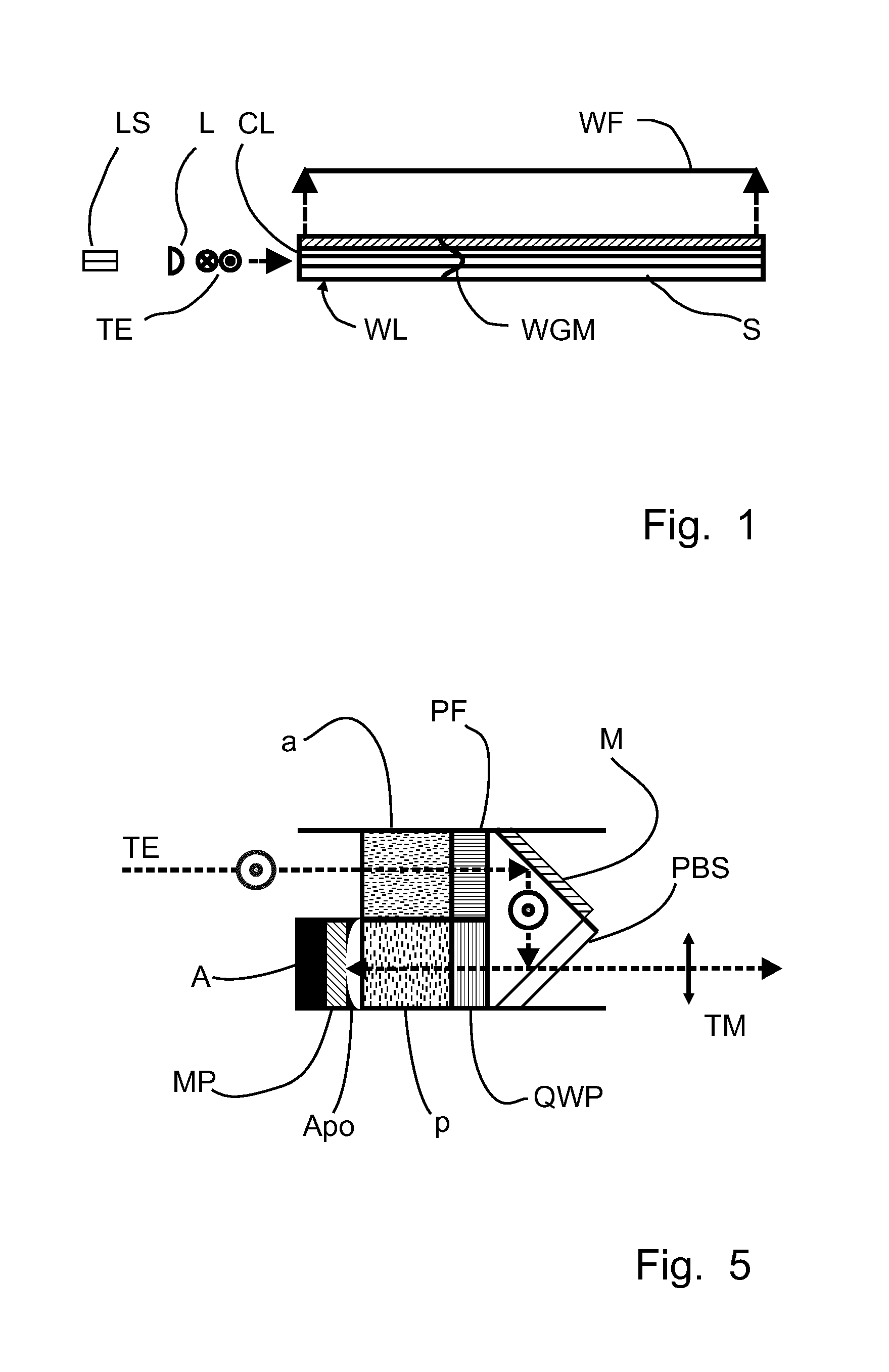
[0139]Now to an optical setup of an illumination unit, FIG. 1 illustrates a first embodiment of a flat illumination unit for a display device,...


PUM

PropertyMeasurementUnit
distanceaaaaaaaaaa
thicknessaaaaaaaaaa
thicknessaaaaaaaaaa

Abstract

The invention relates to a display device for holographic reconstruction. The display device comprises a spatial light modulator device having combined phase modulating pixels and amplitude modulating pixels, an illumination unit generating sufficiently coherent light and arranged to illuminate of the spatial light modulator device and a reflection plane. The device being arranged such that light enters the spatial light modulator device and passes both the phase modulating pixel and the amplitude modulating pixel of the spatial light modulator device. The light is reflected by the reflection plane in between.

Description

CROSS-REFERENCE TO RELATED APPLICATIONS[0001]This application claims the priority of PCT / EP2015 / 050050, filed on Jan. 5, 2015, which claims priority to EP Application No. 14150286.4, filed on Jan. 7, 2014, the entire contents of each of which are incorporated fully herein by reference.BACKGROUND OF THE INVENTION[0002]The present invention relates to a display device for holographic reconstruction. In particular the present invention relates to a display device using in particular a planar combination of adjacent modulating pixels of a spatial light modulator device. Such display devices are required mostly for mobile applications like smart phones and tablet computers. However, other applications are also possible[0003]Furthermore, the present invention relates also to a method of generating a holographic reconstruction and a spatial light modulator device applied in such a display device for generating at least one of a two-dimensional and / or three-dimensional representation of a s...

Claims


Application Information

Patent Timeline
Patent Type & Authority Applications(United States)
IPC IPC(8): G03H1/22G02B26/08G03H1/02G02B26/06G02F1/1335
CPCG03H1/2294G02B26/06G02F1/133553G03H1/2286G03H1/02G03H2225/34G03H2001/0224G03H2222/18G03H2223/20G03H2223/22G02B26/0833G02F2203/50G03H2225/36G03H2225/55G03H2225/22G03H2225/24G03H2225/33G03H2223/24G03H2001/0858G03H2223/19G03H2222/35G03H2223/16G03H1/2205G02F1/133538G02F1/133616
Inventor FUTTERER, GERALD
Owner SEEREAL TECHNOLOGIES
Why Eureka
Try Eureka