

Isotropic Harmonic Oscillator and Associated Time Base Without Escapement or With Simplified Escapement
a timekeeper and harmonic oscillator technology, applied in the field of timekeepers, can solve the problems of not being able to clearly disclose the application of the principles exposed to a timekeeper such as a watch
- Summary
- Abstract
- Description
- Claims
- Application Information
AI Technical Summary
Benefits of technology
Problems solved by technology
Method used
Image

Examples
Embodiment Construction
[0033]The present invention will be better understood from the following description and from the drawings which show
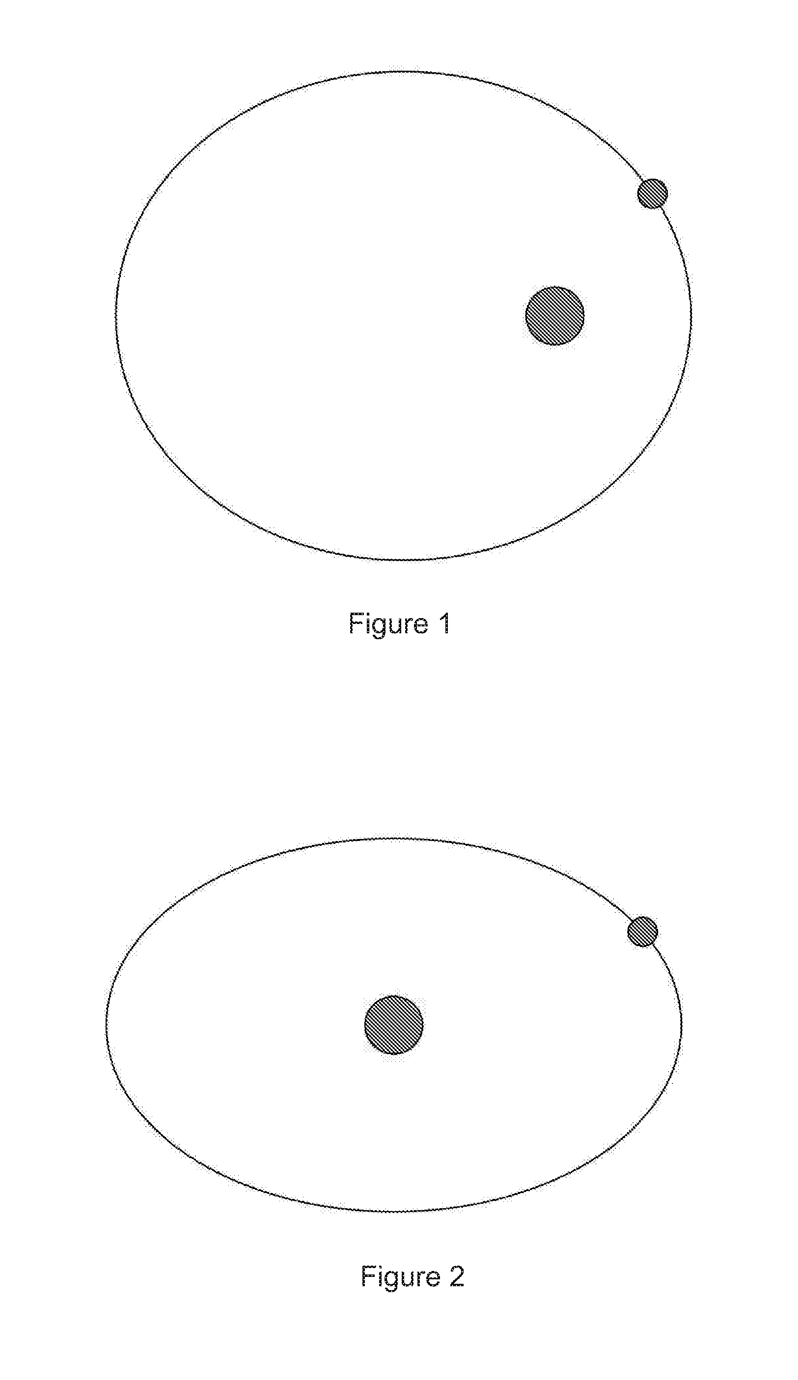
[0034]FIG. 1 illustrates an orbit with the inverse square law;
[0035]FIG. 2 illustrates an orbit according to Hooke's law;
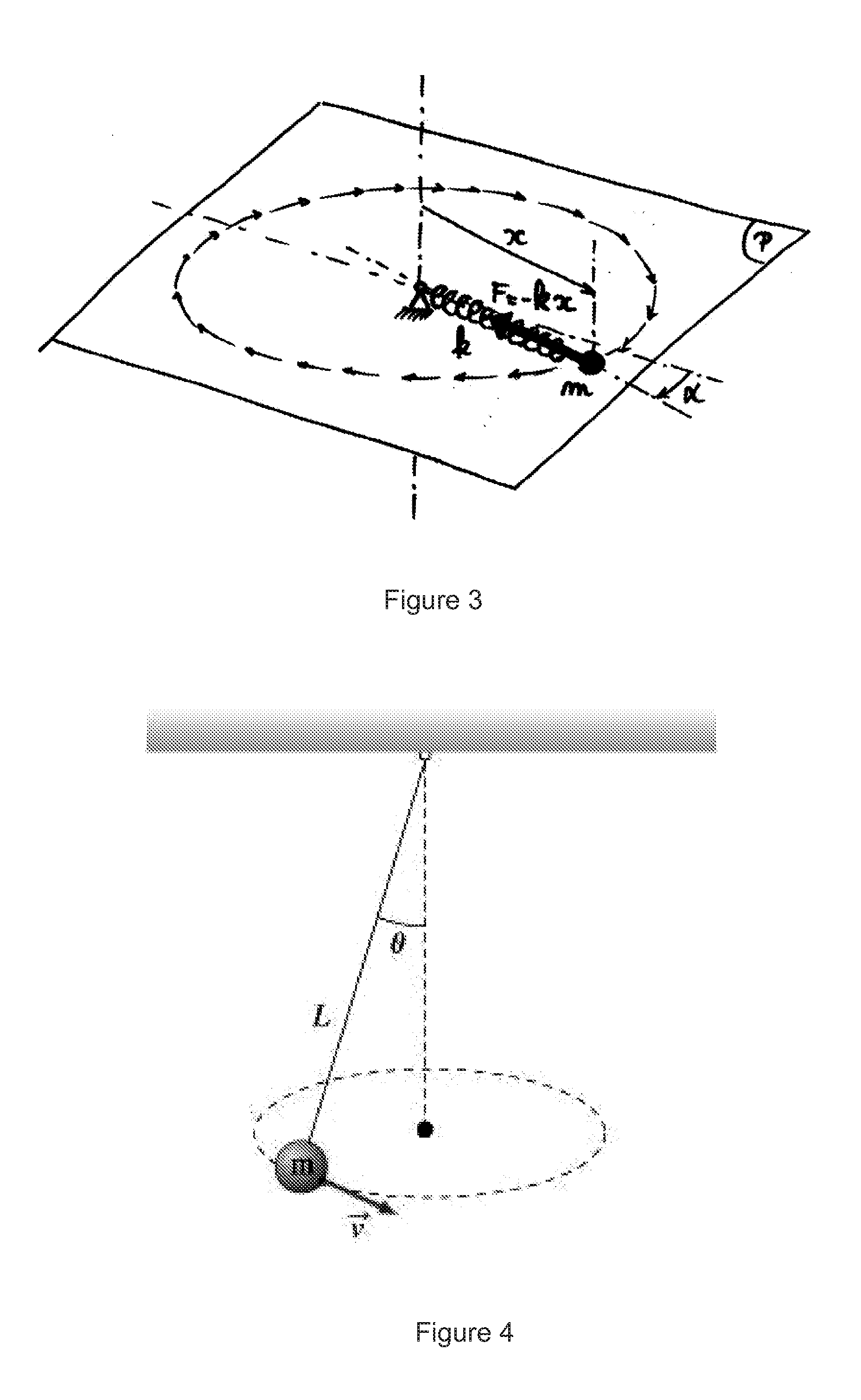
[0036]FIG. 3 illustrates an example of a physical realization of Hooke's law;
[0037]FIG. 4 illustrates the conical pendulum principle;
[0038]FIG. 5 illustrates a conical pendulum mechanism;
[0039]FIG. 6 illustrates a Villarceau governor made by Antoine Breguet;
[0040]FIG. 7 illustrates the propagation of a singularity for a plucked string;
[0041]FIG. 8 illustrates a rotating spring on a turntable;
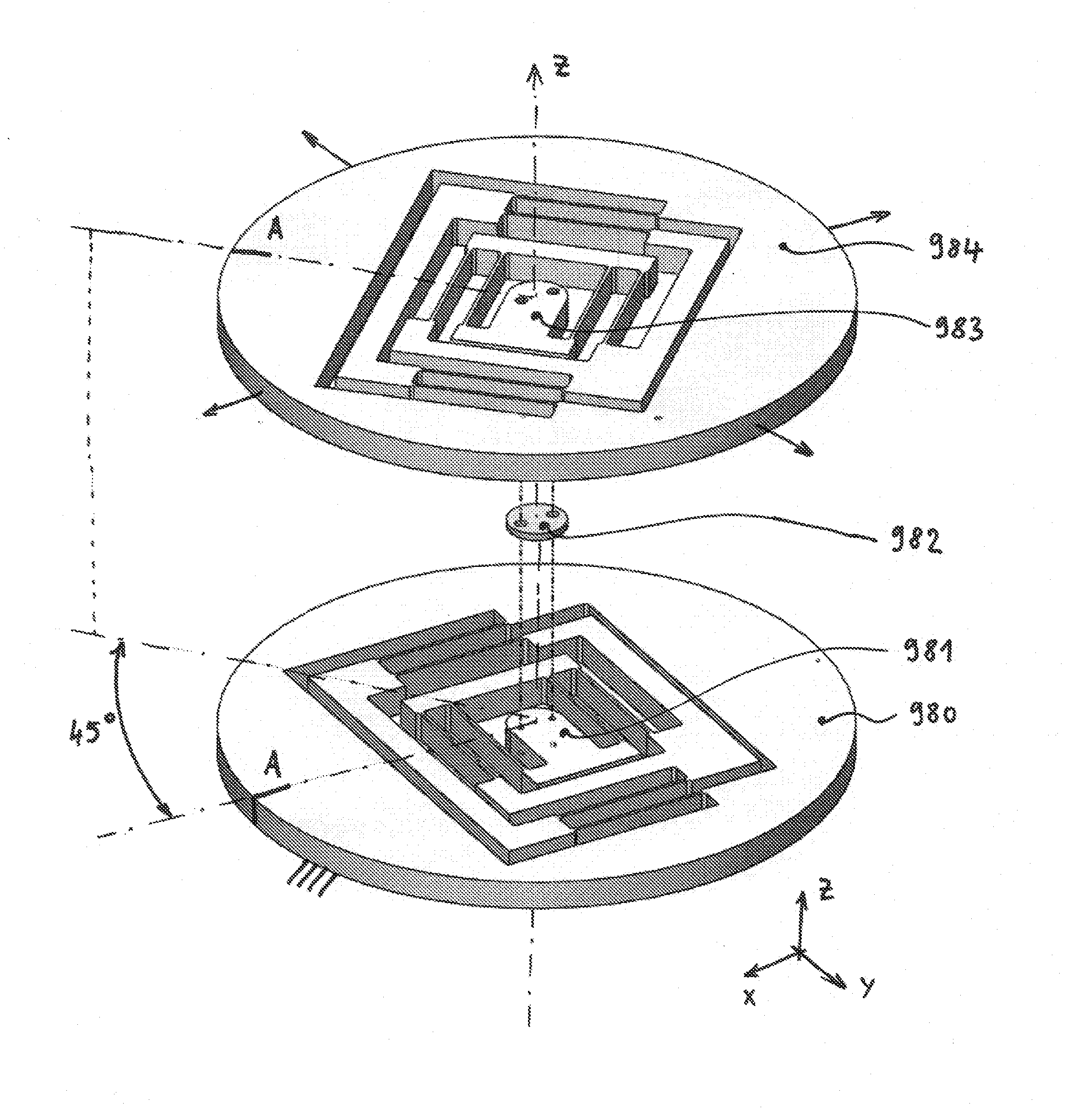
[0042]FIG. 9 illustrates an isotropic oscillator with axial spring and support;
[0043]FIG. 10 illustrates an isotropic oscillator with double leaf springs;
[0044]FIG. 11 illustrates an XY stage comprising two serial compliant four-bars mechanisms;
[0045]FIG. 12 illustrates an XY stage comprising four parallel arms linked with eight spherical joints and a bellow con...
PUM
 Abstract
Description
Claims
Application Information