

Up-drawing continuous casting method, up-drawing continuous casting apparatus, and continuous casting
- Summary
- Abstract
- Description
- Claims
- Application Information
AI Technical Summary
Benefits of technology
Problems solved by technology
Method used
Image

Examples
embodiment 1
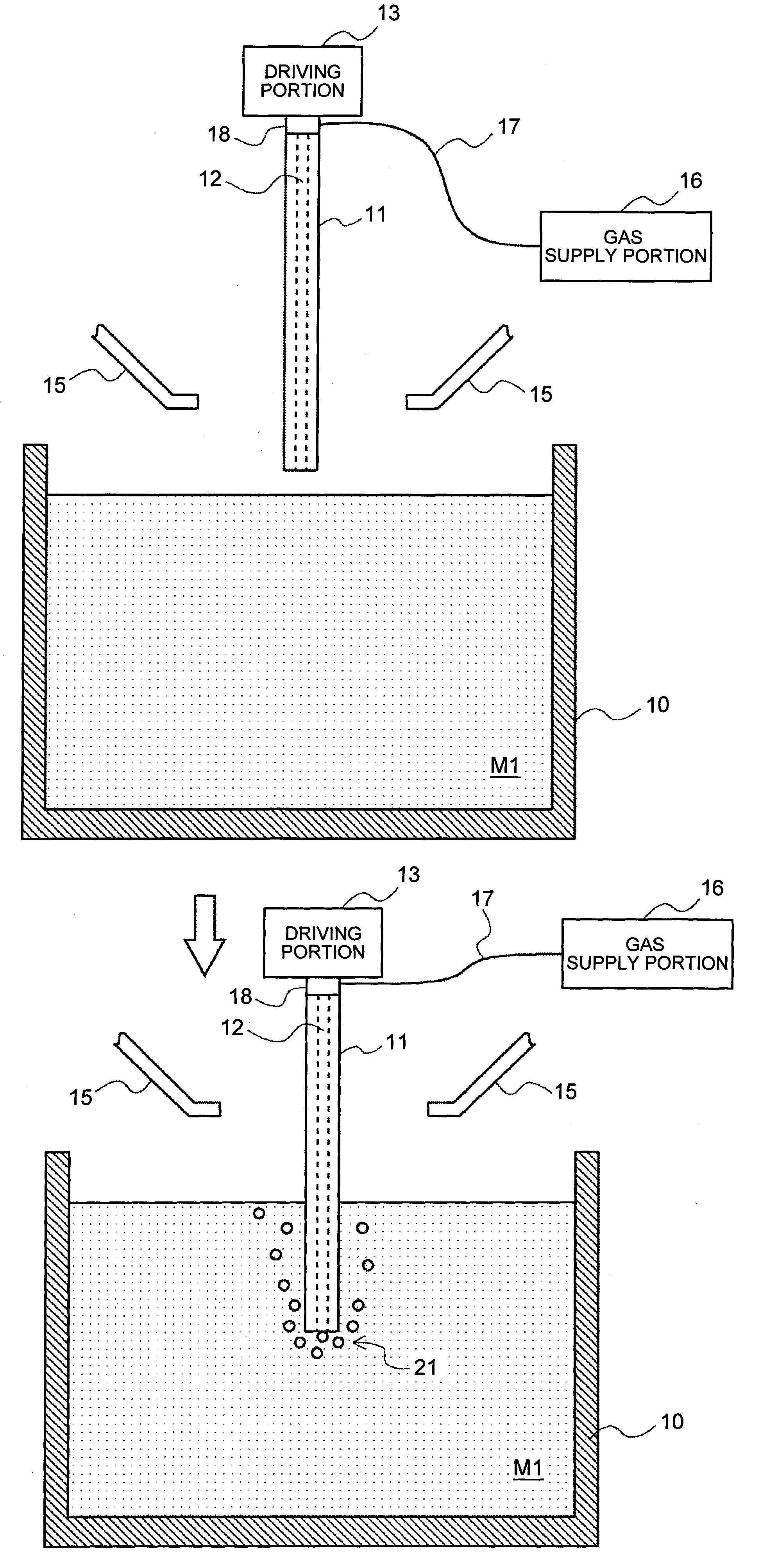
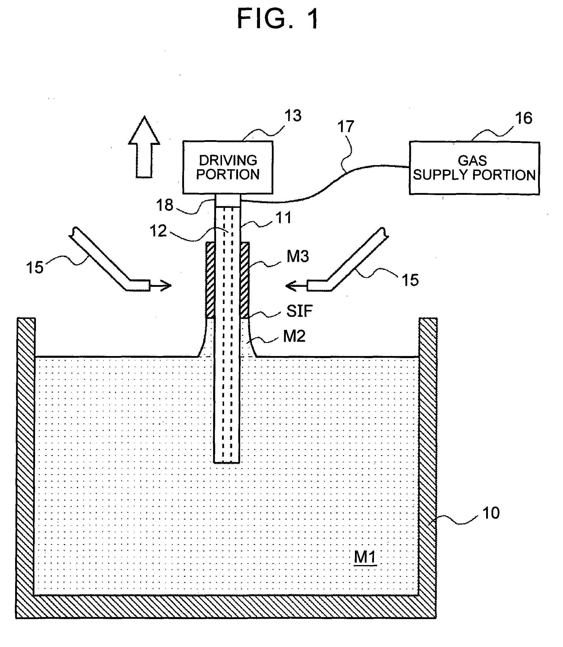
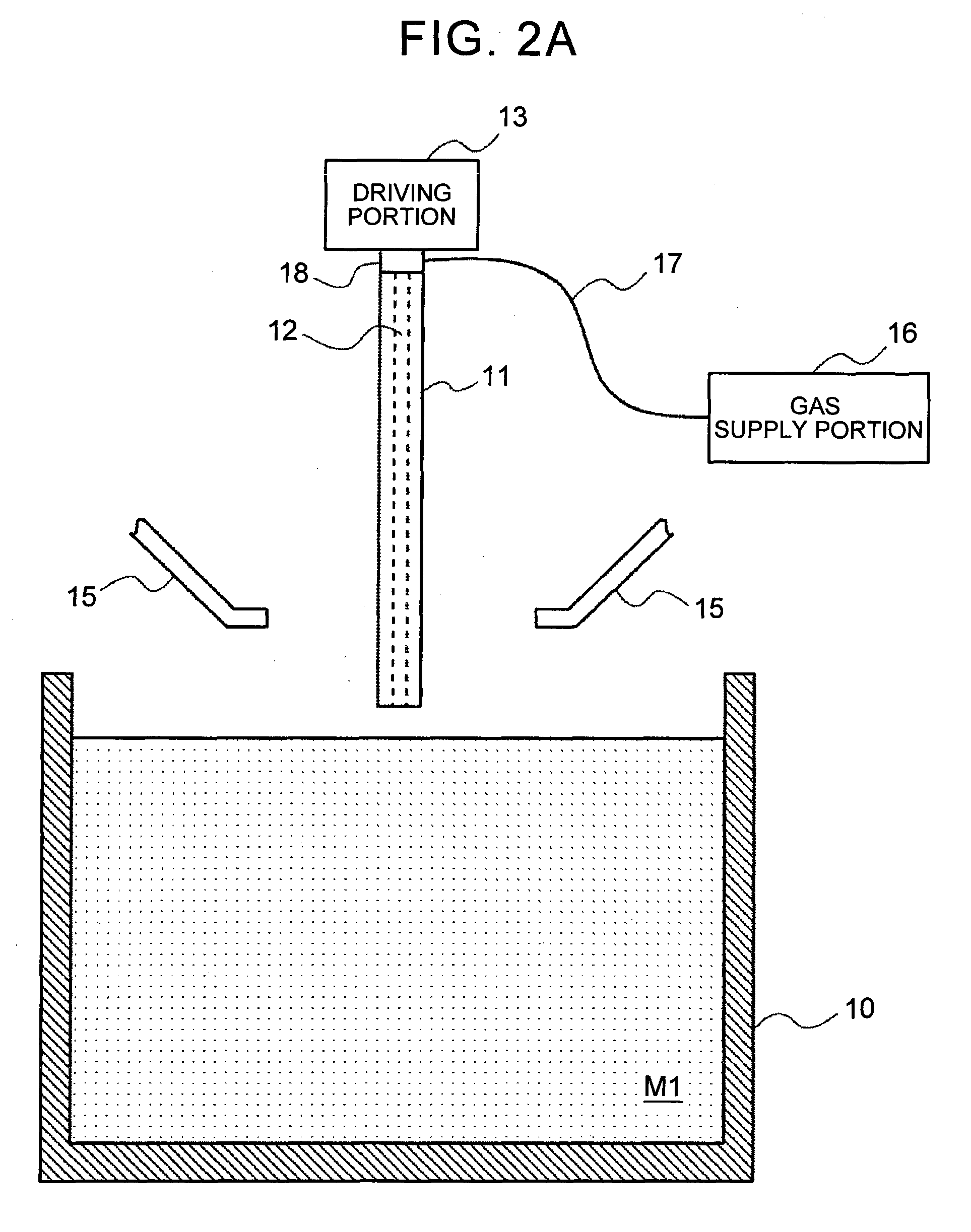
[0038]With reference to drawings, the following describes embodiments of the present invention. FIG. 1 is a sectional view to describe an up-drawing continuous casting apparatus according to Embodiment 1. The up-drawing continuous casting apparatus according to the present embodiment forms a casting having a predetermined shape while drawing up molten metal. As illustrated in FIG. 1, the up-drawing casting apparatus according to the present embodiment includes a holding furnace. 10, a hollow member 11, a driving portion 13, a cooling portion 15, and a gas supply portion 16.
[0039]The holding furnace 10 holds molten metal M1. The molten metal M1 is molten metal of aluminum or aluminum alloy, for example. The holding furnace 10 holds the molten metal M1 at a temperature of a melting point or more of a material constituting the molten metal M1. In the example in FIG. 1, molten metal is not replenished into the holding furnace 10 during casting, so that a surface level of the molten meta...
embodiment 2
[0063]Next will be described Embodiment 2 of the present invention. FIG. 5 is a sectional view to describe an up-drawing continuous casting apparatus according to Embodiment 2. The up-drawing continuous casting apparatus illustrated in FIG. 5 is different from the up-drawing continuous casting apparatus (see FIG. 1) described in Embodiment 1 in that a shape determining member 25 is provided. Except for the above point, the up-drawing continuous casting apparatus of Embodiment 2 is the same as the up-drawing continuous casting apparatus described in Embodiment 1, so the same reference sign is assigned to the same constituent and duplicate description is omitted.
[0064]The shape determining member 25 is a member configured to determine a shape (a sectional shape) of a casting M3 by applying, to molten metal M1, an external force (that is, a force that acts on the molten metal M1 at the time when the molten metal M1 passes through a molten metal passage portion 26), when the molten meta...
embodiment 3
[0073]Next will be described Embodiment 3 of the present invention. Embodiments 1, 2 deal with a case where a casting is formed by use of one hollow member. Embodiment 3 deals with a case where a casting is formed by use of a plurality of hollow members. Note that the following exemplary castings are merely examples, and castings having other various shapes can be formed in an up-drawing continuous casting method according to the present invention. Note that an up-drawing continuous casting apparatus for use in the present embodiment is the same as the up-drawing continuous casting apparatus as described in Embodiments 1, 2, so duplicate-description is omitted.
[0074]FIGS. 7 to 17 are perspective views each illustrating an example of the placement of hollow members at the time of forming a casting by use of the up-drawing continuous casting method according to the present embodiment, and an example of the casting thus formed. For example, a plurality of hollow members may be placed s...
PUM
| Property | Measurement | Unit |
|---|---|---|
| Shape | aaaaa | aaaaa |
| Surface tension | aaaaa | aaaaa |
| Wettability | aaaaa | aaaaa |
Abstract
Description
Claims
Application Information