Folding wing tip and rotating locking device

a locking device and wing tip technology, applied in the direction of air-flow influencers, aircraft components, power plants, etc., can solve problems such as rotation of disks, achieve the effects of improving the combined load bearing capacity of the locking mechanism, reducing maintenance or repair time, and improving the load bearing capacity of the wing tip device and the inner wing interfa

Active Publication Date: 2016-11-17
AIRBUS OPERATIONS LTD
View PDF1 Cites 7 Cited by
  • Summary
  • Abstract
  • Description
  • Claims
  • Application Information

AI Technical Summary

Benefits of technology

[0006]The rotatable locking member acts to preload the locking mechanism, such that any wear of the rotatable locking member and / or the locking pin is compensated for, thereby reducing the chances of play developing in the locking mechanism. The aircraft wing may comprise a first stop, into which the locking pin comes into contact when wing tip device is in the locked flight configuration, with the rotatable locking member acting to pull the locking pin against the first stop when in the locked position. Such an arrangement is advantageous because the first stop provides another point of contact for the locking pin, which when the wing tip device is in the locked flight configuration, provides another bearing surface for loads passing through the locking pin to react against. The aircraft wing may comprise a second stop, into which the locking pin comes into contact when the wing tip device is in the locked flight configuration, with the rotatable locking member acting to pull the locking pin against the second stop when in the locked position. Such an arrangement is advantageous because the second stop provides another point of contact for the locking pin, which when the wing tip device is in the locked flight configuration, provides another bearing surface for loads passing through the locking pin to react against. Providing a number of bearing surfaces for loads passing through the locking pin to react against may improve the stability and / or strength of the locking mechanism.
[0008]The aircraft wing may comprise a second locking mechanism. The second locking mechanism may comprise comprising a guide surface arranged to guide the locking pin during rotation of the second rotatable locking member to a locked configuration, in which the guide surface is shaped such that the locking pin is urged towards the rotation axis of the second rotatable locking member by a camming action of the groove on the locking pin, thereby preloading the second locking mechanism. Where the first locking mechanism and second locking mechanism engage with the same locking pin, the locking pin may comprise a split bearing, such that a first outer surface of the locking pin may rotate relative to, and possibly independently of, a second outer surface of the locking pin. The split bearing may act to reduce the friction between the guide surfaces of the first locking mechanism and second locking mechanism and the locking pin which may be created when engaging and disengaging the locking mechanism, as the outer surfaces of the locking pin, which are guided by the guide surface, may rotate when being guided into and out of the locked configuration. Reducing the friction in this way may reduce wear of the components, and also reduce the torque required to engage and disengage the locking mechanism. The reduced friction may also reduce the possibility of the components becoming jammed. The locking pin may comprise an additional engagement surface which is rotatable relative to the surfaces intended for engagement with the first locking mechanism and second locking mechanism. This engagement surface may be urged against the first stop and / or second stop when the locking mechanisms are in the locked configuration.
[0010]The second locking mechanism may be arranged to rotate in a plane parallel to the first locking mechanism but in the opposite direction. Providing such an arrangement may improve the load bearing capacity of the wing tip device and inner wing interface. The first locking mechanism and second locking mechanism may have the same axis of rotation.
[0011]Alternatively, the first locking mechanism and second locking mechanism may have different axes of rotation. Providing the first locking mechanism and second locking mechanism with different axes of rotation may increase the combined load bearing capabilities of the locking mechanisms, allowing loads in several different directions to reacted through the first and second rotating locking mechanisms in different directions.
[0012]The aircraft wing may comprise a plurality of locking mechanisms as described, for example in a modular configuration, such that the locking mechanisms may be replaced or repaired as a modular unit, thereby reducing maintenance or repair time.

Problems solved by technology

Rotation of the toothed drive mechanism may result in the rotation of the disk around the rotation axis of the disk.

Method used


Image

  • Folding wing tip and rotating locking device
  • Folding wing tip and rotating locking device
  • Folding wing tip and rotating locking device

Examples


first embodiment

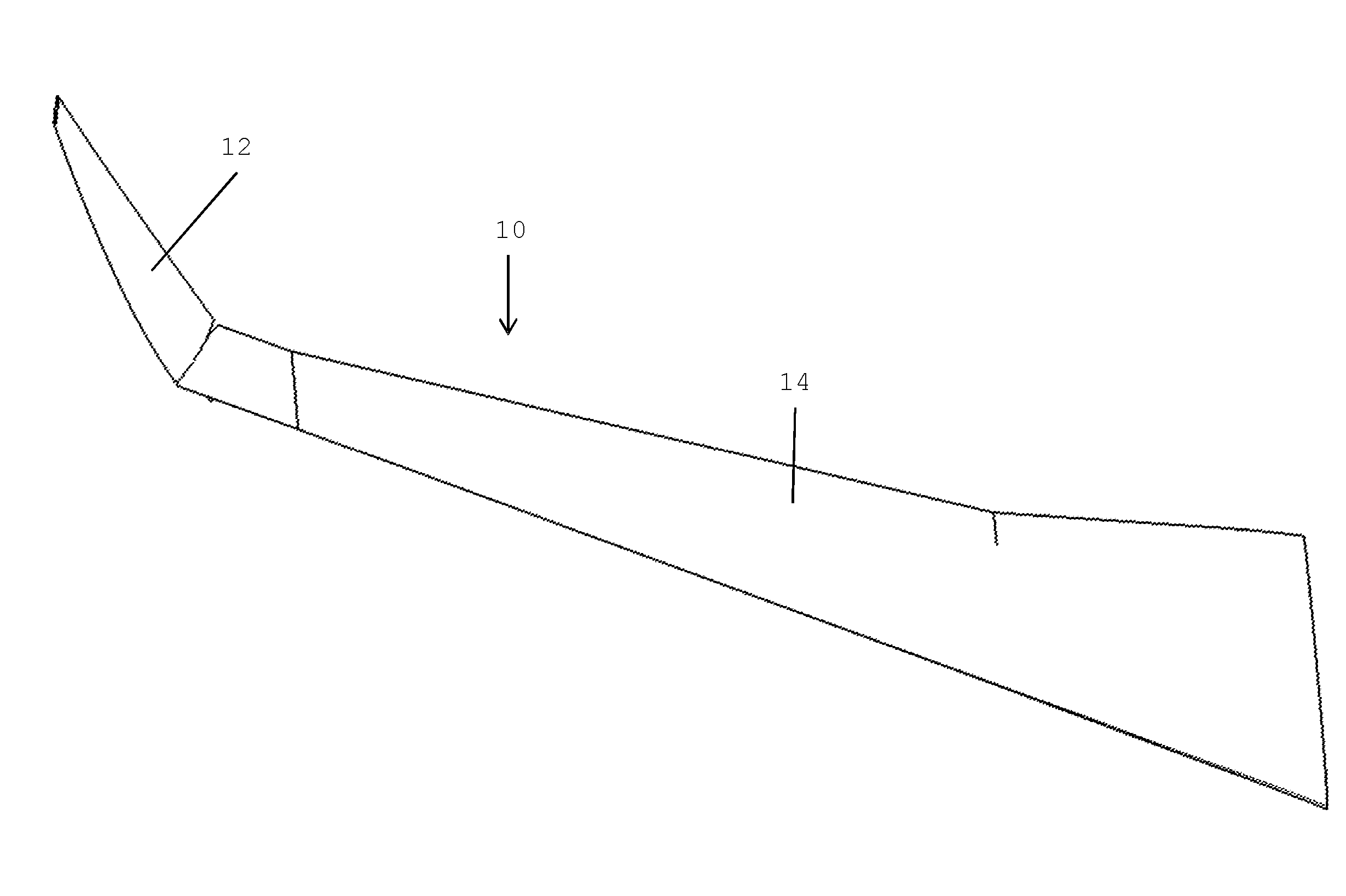
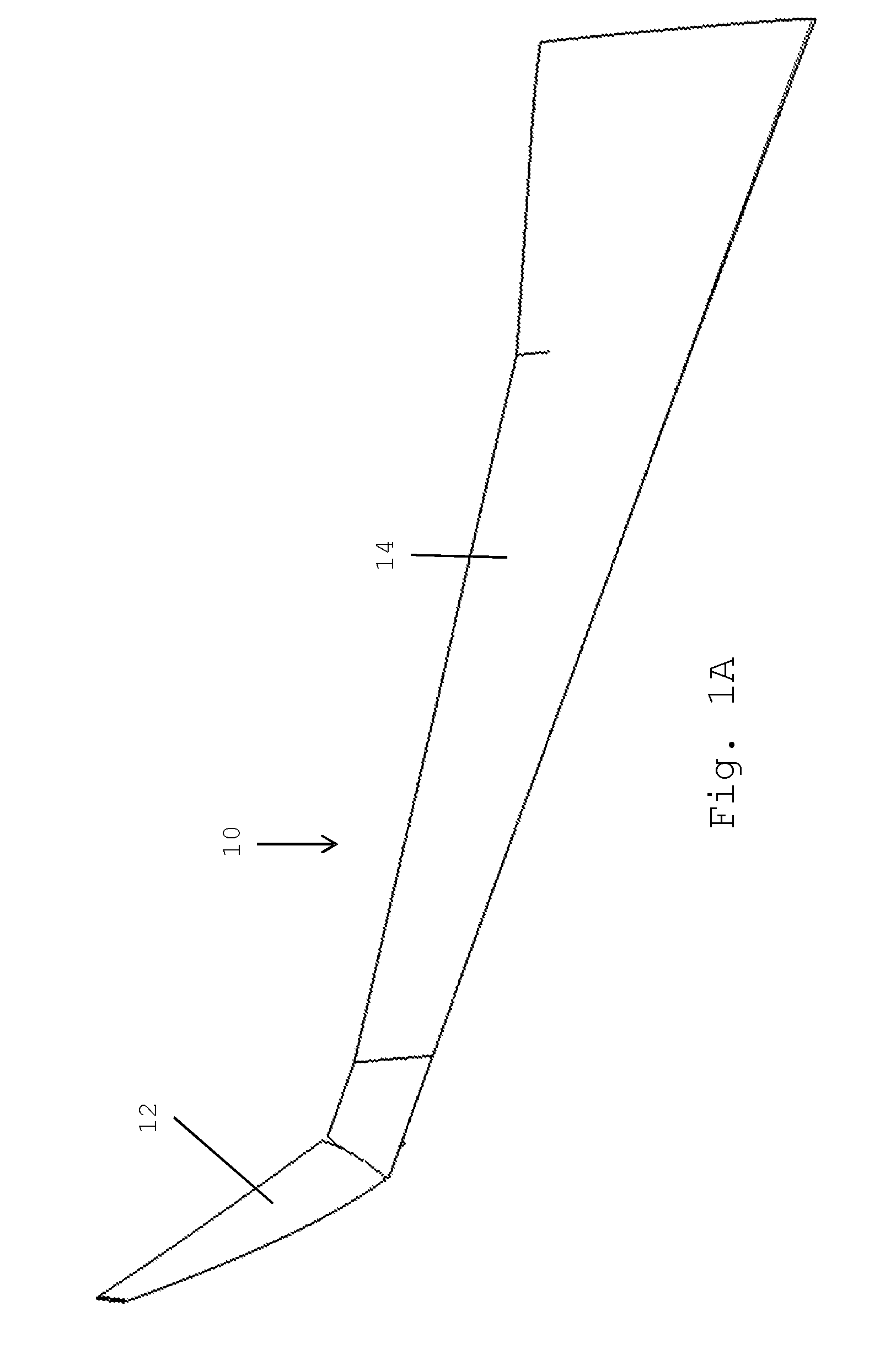
[0031]FIG. 2 shows a partial view of a locking mechanism 20 according to the invention, which comprises a rotatable disk 22, with a cut away section including a groove 24 which provides a guide surface for guiding a locking pin. The disk is rotatably mounted around an axis of rotation X. Shown in the locked position, the disk 22 is mounted to a fixed wing 14 via a supporting member. The guide surface provided by the groove 24 includes an outer portion 26 and an inner portion 28, with a smooth guide surface 30 extending from the outer portion 26 to the inner portion 28. The distance between a point on the outer portion 26 of the guide surface and the axis of rotation X is greater than the distance between a point on the inner portion 28 of the guide surface and the axis of rotation X, meaning that as a locking pin is guided along the guide surface, it is effectively pulled towards the axis of rotation X. FIG. 2 also shows a locking pin 32 located in contact with the inner portion 28,...

second embodiment

[0033]FIG. 3 shows the invention, with a first disk 22 as described with reference to FIG. 2, and a second disk 22′, the same shape as the first disk 22, with the same axis of rotation X, but flipped in orientation, so the disk 22′ rotates in the opposite direction to the disk 22 to engage and disengage with the locking pin 32. FIG. 3 also shows a drive mechanism 40, which drives the rotation of the disk 22 in one direction whilst also driving the rotation of the disk 22′ in the opposite direction. This may be by a tooth and ratchet arrangement for each disk 20, 22′, or any other suitable drive mechanism as will be appreciated by the skilled person. FIG. 4 also shows a support arm 42 to which the locking disks 22, 22′ are rotatably mounted, and stops 44 and 46 in the form of rotatable rollers. The stops 44 and 46 are brought into contact with the locking pin 32 as described with reference to FIG. 2.

third embodiment

[0034]FIG. 5 shows the invention. FIG. 5 shows a first disk 222 and second disk 222′, in a similar configuration to that described in FIGS. 3 and 4, though with the axes of rotation X, X′ of the first disk 222 and second disk 222′ spaced apart from each other. As can be seen, this arrangement provides the locking pin 232 with bearing surfaces at different points, allowing loads experienced by the locking pin 232 to be reacted in different directions.

[0035]FIG. 6 shows a locking pin 600 which may be used as part of a locking mechanism as described in the above embodiments of the invention. The locking pin 600 comprises a central pin 602 on which a first rotatable outer surface 604 and second rotatable outer surface 606 is mounted. The two outer surfaces 604, 606, are located to be guided by the guide surfaces of the first locking mechanism and second locking mechanism, and are free to rotate whilst being guided. The arrows in FIG. 6 indicate that the outer surfaces may rotate indepen...


PUM


Abstract

The invention provides an aircraft wing, comprising a fixed wing and a wing tip device at the tip. The wing tip device is configurable between: (i) a locked flight configuration for use during flight and (ii) a ground configuration for use during ground-based operations. The wing further comprises a locking mechanism for locking the folding wing tip device in the locked flight configuration. A rotatable locking member is associated with one of the folding wing tip device and the fixed wing, and a locking pin associated with the other. The rotatable locking member comprises a guide surface to guide the locking pin to a locked configuration, in which the guide surface is shaped such that the locking pin is urged toward the rotation axis of the rotatable locking member by a camming action of the guide surface on the locking pin, thereby preloading the locking mechanism.

Description

BACKGROUND OF THE INVENTION[0001]There is a trend towards increasingly large passenger aircraft, for which it is desirable to have correspondingly large wing spans. However, the maximum aircraft span is effectively limited by airport operating rules which govern various clearances required when maneuvering around the airport (such as the span and / or ground clearance required for gate entry and safe taxiway usage).[0002]Therefore, folding wing tip devices have been introduced into passenger aircraft, where a wing tip device is movable between a flight configuration for use during flight, and a ground configuration for use during ground-based operations. In the ground configuration, the wing tip device is moved away from the flight configuration such that the span of the aircraft wing is reduced, thereby allowing use of existing gates and safe taxiway usage.[0003]In order to securely fasten the folding wing tip device in the flight configuration, one or more locking mechanisms must be...

Claims


Application Information

Patent Timeline
Patent Type & Authority Applications(United States)
IPC IPC(8): B64C3/56B64C13/28
CPCB64C13/28B64C3/56B64C23/072Y02T50/10
Inventor KORYA, CHETANBRYANT, ANTHONYHARDING, MATTBRAKES, DAVID
Owner AIRBUS OPERATIONS LTD
Why Eureka
Try Eureka