Rescue elevator system

a technology of elevator system and elevator, which is applied in the direction of lifting devices, constructions, buildings, etc., to achieve the effect of avoiding disadvantageous forces on the rescue ladder, improving the transmission of elevator drive, and avoiding disadvantageous forces

Active Publication Date: 2016-11-24
IVECO MAGIRUS
View PDF0 Cites 2 Cited by
  • Summary
  • Abstract
  • Description
  • Claims
  • Application Information

AI Technical Summary

Benefits of technology

[0007]It is therefore an object of the present invention to provide a rescue elevator system of the above kind with an improved force transmission of the elevator drive from the rope winch to the suspension point at the elevator, avoiding disadvantageous forces on the rescue ladder and on the elevator, and enabling a smooth course towards the free end of the ladder to approach it as near as possible, thereby providing a safe passage into the elevator from the end of the rescue ladder, for example, from a rescue cage mounted thereon.

Problems solved by technology

As a consequence, the elevator can be pulled towards the end of the rescue ladder further than with a suspension point commonly located near the leading end of the elevator, because unfavourable loads acting in a perpendicular direction to the rails and the framework of the ladder, also having the tendency to raise the elevator, are much lower with a considerable remaining distance between deflection roller and suspension point.

Method used


Image

  • Rescue elevator system
  • Rescue elevator system
  • Rescue elevator system

Examples


Embodiment Construction

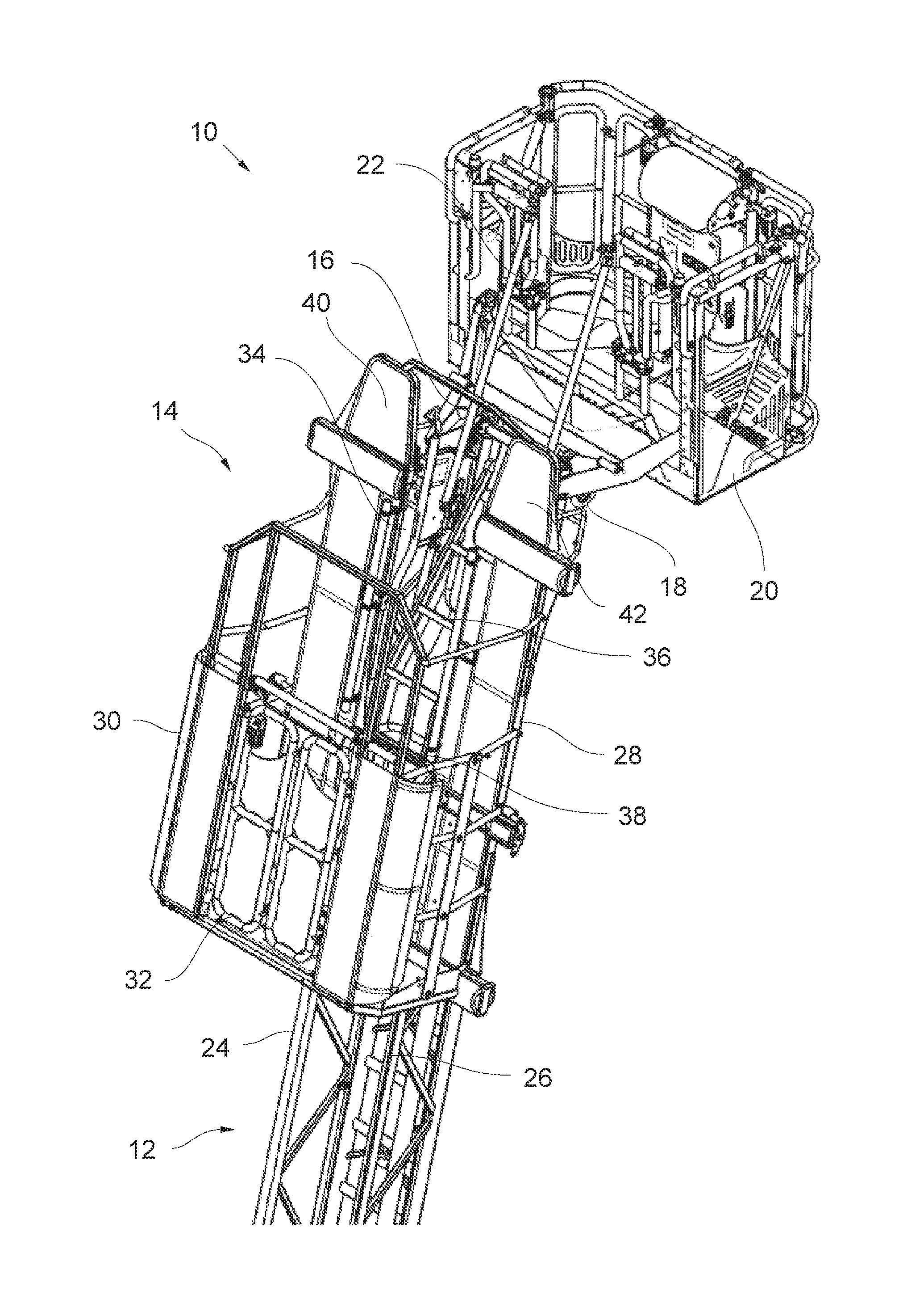
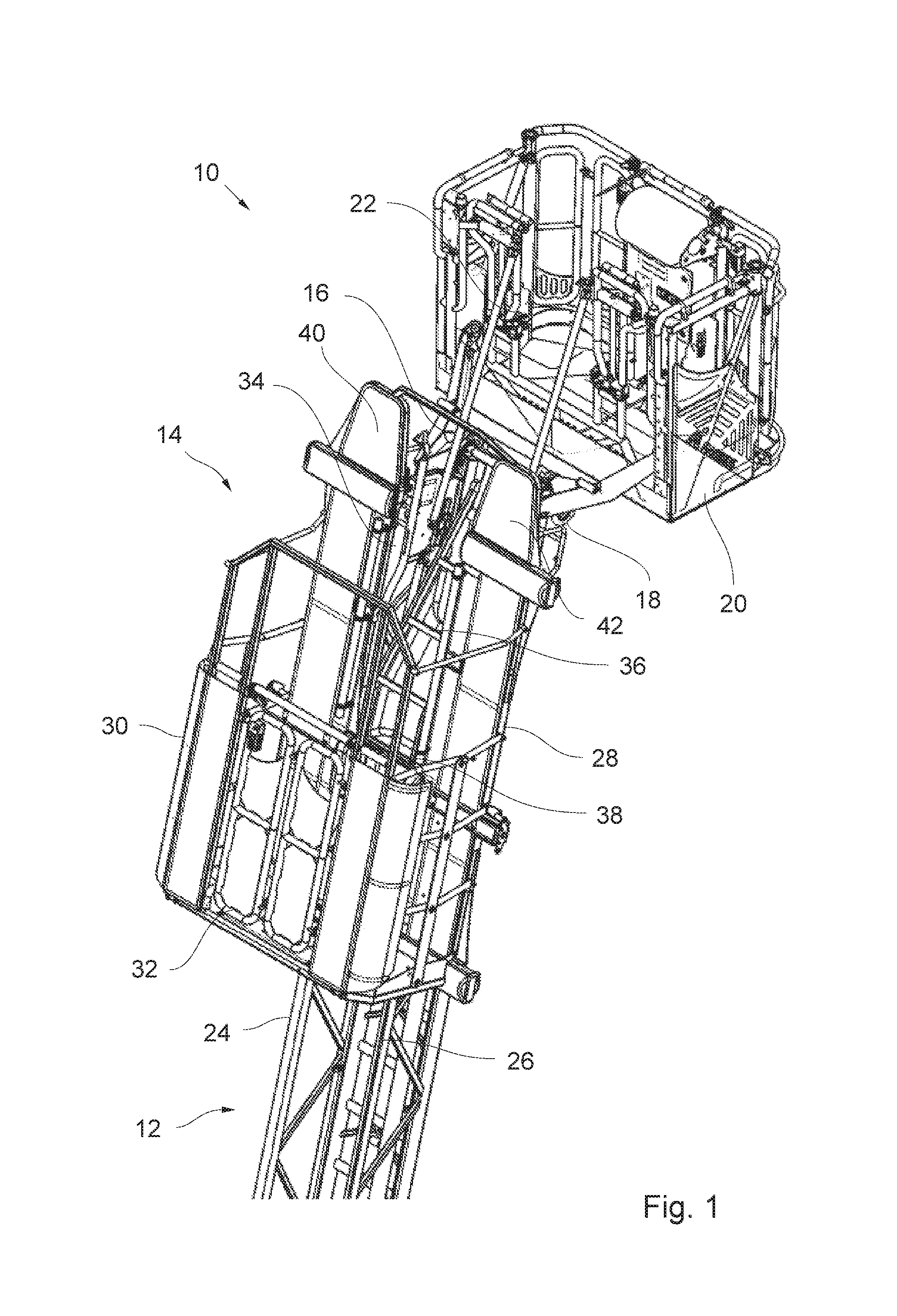
[0020]FIG. 1 shows a rescue elevator system 10 of a firefighting vehicle, comprising a rescue ladder 12 and an elevator 14 that is movable along the rescue ladder 12 up to a movable free end portion 16 of the rescue ladder 12 carrying a rescue cage. The end of the elevator 14 facing this end 16 of the rescue ladder 12 will be designated as the leading end of the elevator 14, related to a course of the elevator 14 towards the free movable end 16 of the rescue ladder 12 carrying a rescue cage in the present example, and the opposite end of the elevator 14 during this course shall be referred to as its trailing end.

[0021]The free end 16 of the rescue ladder 12 comprises a mounting 18 to attach a rescue cage 20 at the rescue ladder 12. The rescue ladder 20 as such is known and shall not be further described in more detail in the following. It has a passage opening 22 at its rear portion such that a passenger can leave the rescue cage 20 through this passage opening 22 to enter the rescu...


PUM


Abstract

Rescue elevator system, comprising a rescue ladder and an elevator running on rails on a top side of the rescue ladder up to an end position at one end of the rescue ladder, and an elevator drive comprising a rope, a rope winch for pulling the rope and a deflection roller over which the rope is guided from the rope winch to a suspension point at the elevator, wherein the deflection roller is disposed below the rails at or near the one end of the rescue ladder, characterized in that the suspension point is displaced towards a trailing end of the elevator averted from the one end of the rescue ladder such that in the end position of the elevator, the suspension point is located in a distance from the deflection roller in the extension direction of the rails, and the elevator comprises a passage ladder to bridge the distance between the suspension point and the deflection roller in the end position of the elevator, said passage ladder lying on top of the rope and being mounted between the rails at a hinge axis perpendicular to the extension direction of the rails and extending generally towards the one end of the rescue ladder such as to be pivotable between a flat position in which it lies generally parallel to the plane of the rails and an inclined position in which it is inclined downwardly towards the bottom side of the rescue ladder.

Description

CROSS-REFERENCE TO RELATED APPLICATIONS[0001]The present application claims priority to European Patent Application No. 15168271.3 filed May 19, 2015, the entirety of the disclosure of which is expressly incorporated herein by reference.STATEMENT RE: FEDERALLY SPONSORED RESEARCH / DEVELOPMENT[0002]Not ApplicableBACKGROUND[0003]The present invention relates to a rescue elevator system, comprising a rescue ladder and an elevator running on rails on a top side of the rescue ladder, according to the features of the preamble of claim 1.[0004]Rescue ladders, like telescopic turnable ladders mounted on firefighting vehicles, are often equipped with rescue elevators that can run along the extension length of the ladder up to their movable free end. Persons to be rescued can enter the elevator at its end position at the free end of the ladder to be transported safely down to the ground. The elevator generally comprises a chassis with rollers running on the rails of the rescue ladder, and a cag...

Claims


Application Information

Patent Timeline
Patent Type & Authority Applications(United States)
IPC IPC(8): A62B1/02E06C7/12E06C5/04B66F11/04
CPCA62B1/02E06C5/04E06C7/12B66F11/046B66F11/04B66F2700/12
Inventor HUEHN, ALEXANDERHOERSCH, HEINER
Owner IVECO MAGIRUS
Why Eureka
Try Eureka