

Underfloor structure of automotive vehicle
a technology for automotive vehicles and underfloors, which is applied in the direction of vehicle body stabilisation, road transportation emission reduction, transportation and packaging, etc., can solve the problems of unavoidable leakage of air in engine rooms, and achieve the effect of reducing the air resistance of the vehicl
- Summary
- Abstract
- Description
- Claims
- Application Information
AI Technical Summary
Benefits of technology
Problems solved by technology
Method used
Image

Examples
Embodiment Construction
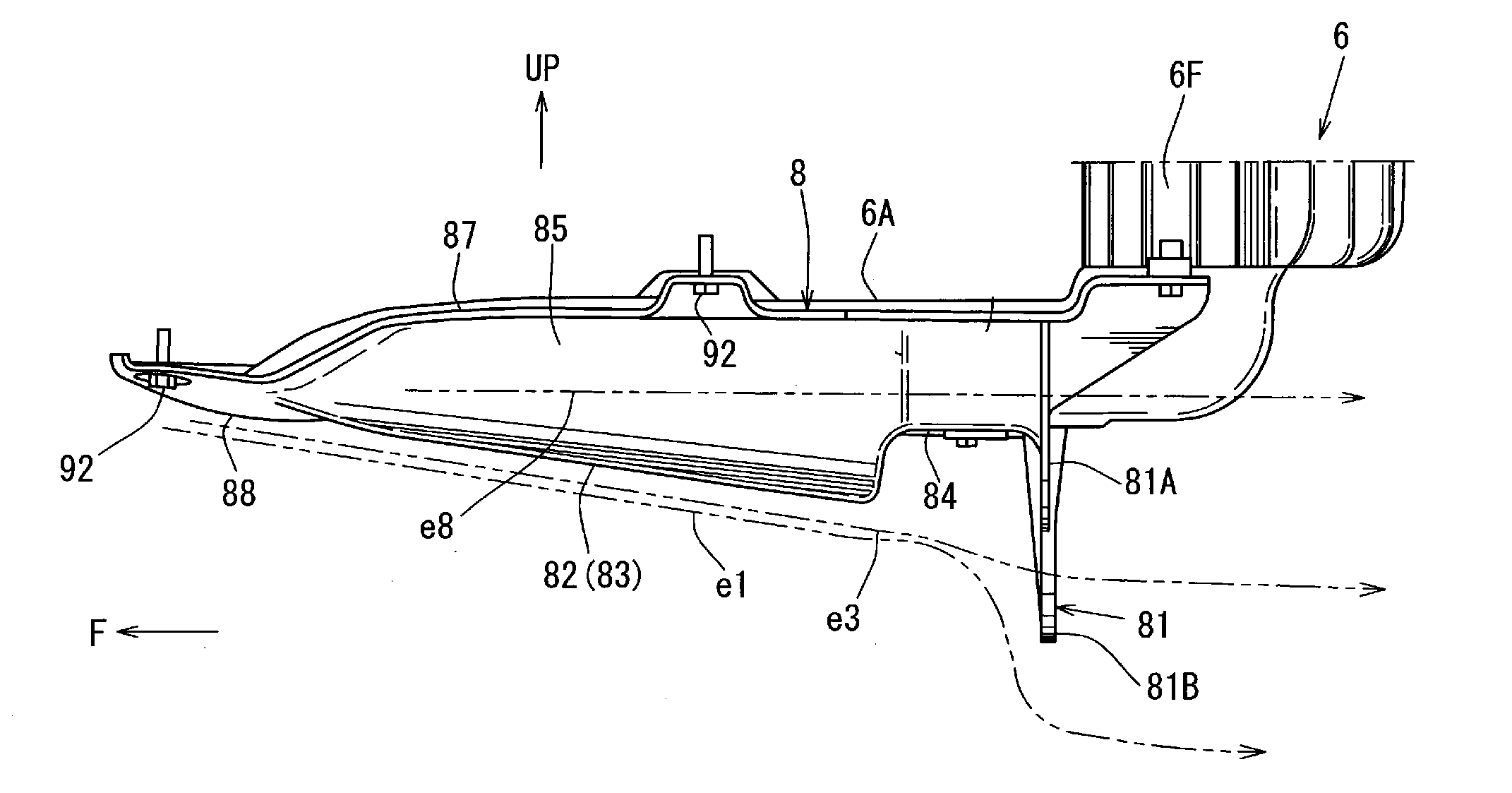
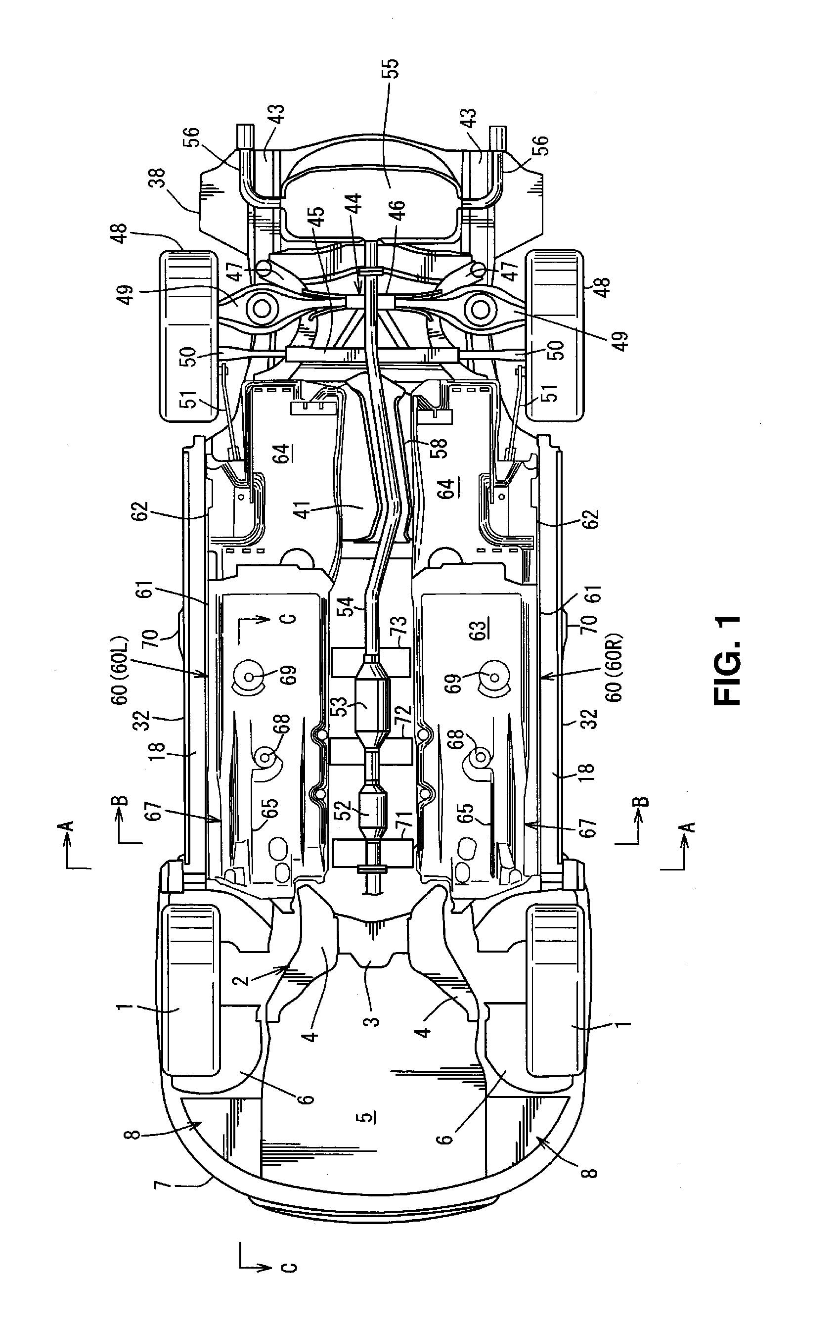
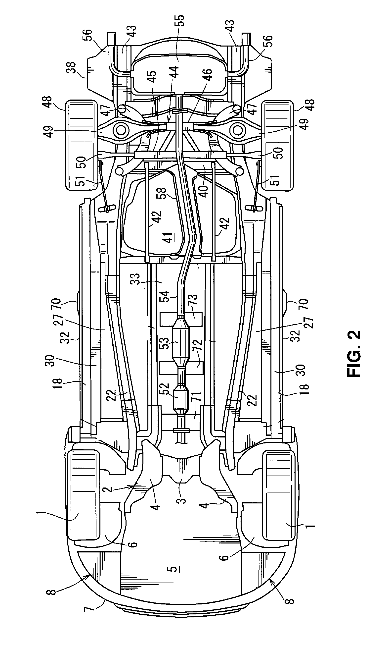
[0028]Hereafter, an embodiment of the present invention will be described specifically referring to the accompanying drawings. The drawings show an underfloor structure of an automotive vehicle, and FIG. 1 is a bottom view of the automotive vehicle provided with the present underfloor structure, FIG. 2 is a bottom view of the automotive vehicle in a state in which right-and-left undercovers are removed from a state shown in FIG. 1, FIG. 3 is a main-part sectional view taken along line A-A of FIG. 1, and FIG. 4 is a sectional view taken along line B-B of FIG. 1.
[0029]As shown in FIGS. 1 and 2, a sub frame 2 for mounting an engine and for attaching a front suspension to suspend a front wheel 1 is provided at a lower portion of an engine room. The sub frame 2 comprises a front cross member (not illustrated) which extends in a vehicle width direction at a front position, a rear cross member 3 which extends in the vehicle width direction at a rear position, and right-and-left side member...
PUM
 Abstract
Description
Claims
Application Information